

Intercom Configuration & Access Management
EK-EK-5DP-VI · EK-ACC-KEY-IP
EK-DEL-4PAN-S / EK-DEL-8PAN-S / EK-DEL-10PAN-S
EK-DEL-10PAN-PL / EK-DEL-15PAN-PL
Introduction
Scope of this manual
This document contains the instructions for the configuration, with the Ekinex Studio software, of an intercom solution based on the following products:
| Name | Description | Model(s) |
|---|---|---|
| DICO | Door phone with face recognition | EK-EK-5DP-VI |
| ACCEDO KEY | IP access-control reader (card / PIN / face), placed at building or apartment level | EK-ACC-KEY-IP |
| DELÉGO PANEL | Several models of wall-mounted touch panels | EK-DEL-4PAN-S, EK-DEL-8PAN-S, EK-DEL-10PAN-S, EK-DEL-10PAN-PL, EK-DEL-15PAN-PL |
This manual is intended for installers and system integrators with a good knowledge of networking and of the related products.
Conventions
| [KEY] | Keyboard keys the installer must press are shown in square brackets. |
| Courier | Software messages generated by Ekinex Studio are written in a monospaced font. |
| Function name | Names of buttons, table fields or other graphic elements of Ekinex Studio are shown in a distinct style. |
Copyright
© Ekinex S.p.A. 2026. This manual and the Ekinex Studio software are subject to copyright; all rights are reserved. Copying, reproduction, translation and/or modification, even partial, are expressly prohibited unless approved in writing by EKINEX®. EKINEX® is a registered trademark of Ekinex S.p.A.
Open source licenses
Ekinex Studio makes use of open source libraries and software components. In case of ownership of one or more related products, for a period of 3 years from the last production date, it is possible to request from EKINEX the source code of the components licensed under the GNU General Public License (GPL) or the GNU Lesser General Public License (LGPL). These components can be used, distributed and modified in accordance with their respective licenses.
EKINEX cannot be held responsible in any way for the source code thus distributed, which is provided without guarantees, nor for any damage resulting from modifications made to this software by third parties unless specifically authorized.
More information
For further information on Ekinex Studio, contact Ekinex technical support at support@ekinex.com. The company reserves the right to make changes to this documentation without notice.
General concepts
The chapters gathered here describe the foundations shared by every Ekinex Studio project, regardless of whether it implements video intercom, access control, or both: the general system overview and software settings, how a project is created and managed, how the building structure is organised, and how devices are added and prepared. The two application domains that build on these foundations, video intercom and access control, are covered in Video intercom and Access control.
Overview
System architecture
The following diagram describes the typical configuration of an intercom system based on Ekinex products, configurable with the Ekinex Studio software:
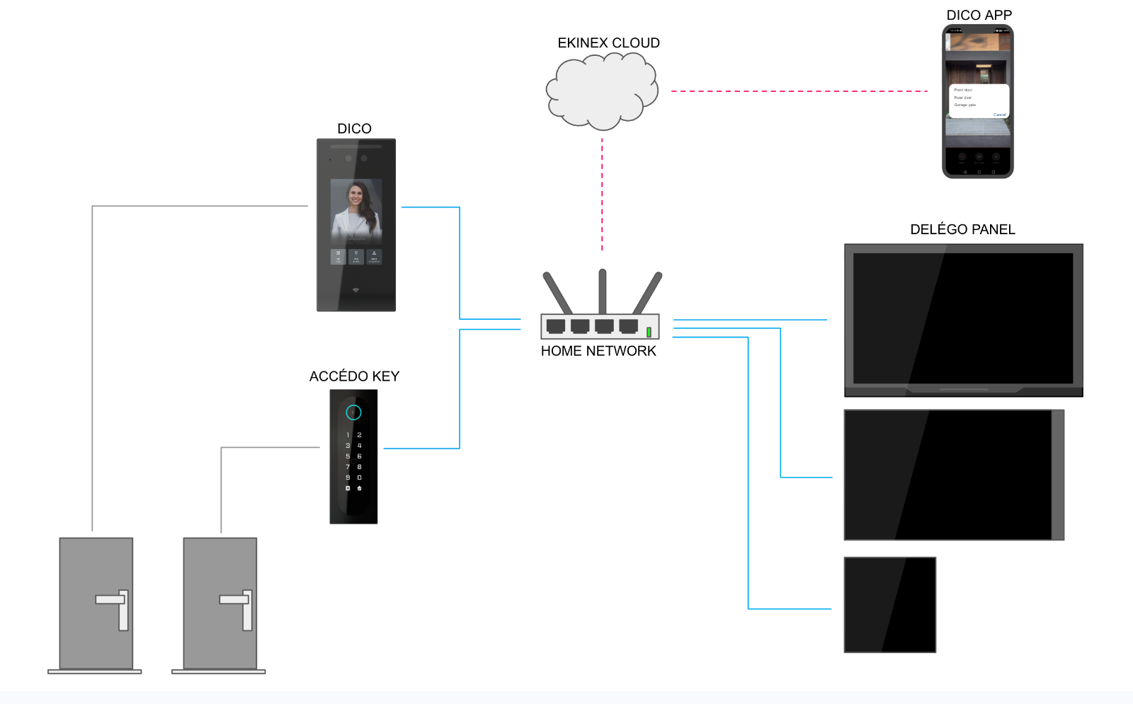
In the local network, one or more DICO door phones can be installed to welcome guests and control doors and gates. Video calls from visitors can be answered on several models of DELÉGO PANEL and, additionally, received on smartphones while on the move.
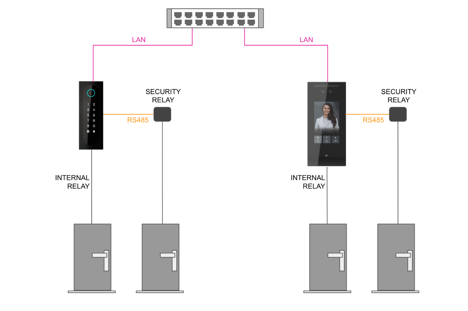
The doors under the control of DICO can be opened in different ways:
- with the internal relay of DICO;
- with a security relay connected to the RS485 port of DICO;
- with a KNX actuator controlled by a Delégo Server.
Requisites
Software requirements
Ekinex Studio can be installed on a computer running one of the following operating systems:
- Windows 11 or higher
- macOS 13 (Ventura) or higher
Firmware requirements
For each product family, a specific minimum firmware version must be present on the devices in order to configure them with Ekinex Studio. The table lists the versions that can be updated directly from Ekinex Studio; devices with older versions must first be updated via their web interface.
| Product | Model | Latest firmware (configure in Studio) | Earlier supported versions (configurable / updatable in Studio) |
|---|---|---|---|
| DICO | EK-EK-5DP-VI | 216.43.0.46 | 216.43.0.31 / .34 / .35 / .42 / .43 |
| Accedo Key | EK-ACC-KEY-IP | 108.43.10.11 | 108.43.10.4 / .9 · 108.43.110.4 / .9 |
| Delégo Panel 4" | EK-DEL-4PAN-S | 51.110.23.85 | 51.110.23.47 / .49 / .50 / .52 / .55 / .56 |
| Delégo Panel 8" | EK-DEL-8PAN-S | 563.43.14.303 | 563.43.12.706 / 563.43.13.303 |
| Delégo Panel 10" | EK-DEL-10PAN-S | 567.43.14.301 | 567.43.13.303 / 567.255.12.773 |
| Delégo Panel 10" PL | EK-DEL-10PAN-PL | 381.110.40.64 | 381.110.40.40 / .41 |
| Delégo Panel 15" PL | EK-DEL-15PAN-PL | 937.43.14.309 | 937.43.14.304 / .308 |
Previous configuration
Ekinex Studio is designed to configure devices that have never been configured manually via their web interface. If a device contains a previous configuration, unpredictable conflicts can occur with the settings applied in Ekinex Studio; proceed at your own risk.
Preliminary operations
Software installation
Install Ekinex Studio using the SETUP on Windows or the DMG on macOS, like any other standard software, and accept the permissions requested for network interaction and notifications.
Devices connection
Connect the DICO door phone(s) and the DELÉGO PANEL(s) to the same network subnet, using a PoE switch or PoE injectors; alternatively, a dedicated power supply can be used. It is not necessary to identify the connected devices on the network, nor to perform any preliminary configuration on the display or the integrated web interface.
Ekinex cloud account
An Ekinex cloud account is required to use Ekinex Studio. The first time the software is opened, enter the user e-mail and the corresponding password:
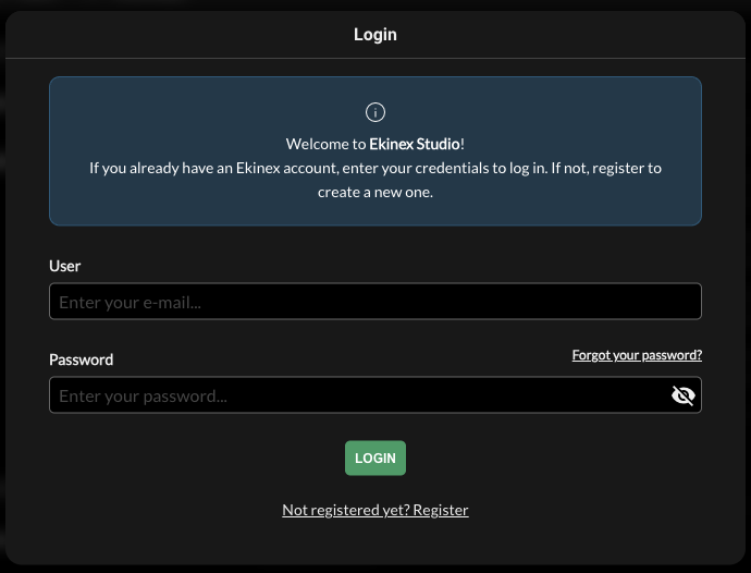
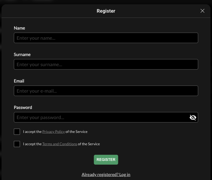
If you do not yet own an account, create one for free using the link at the bottom of the dialog and filling in the requested information:
Settings
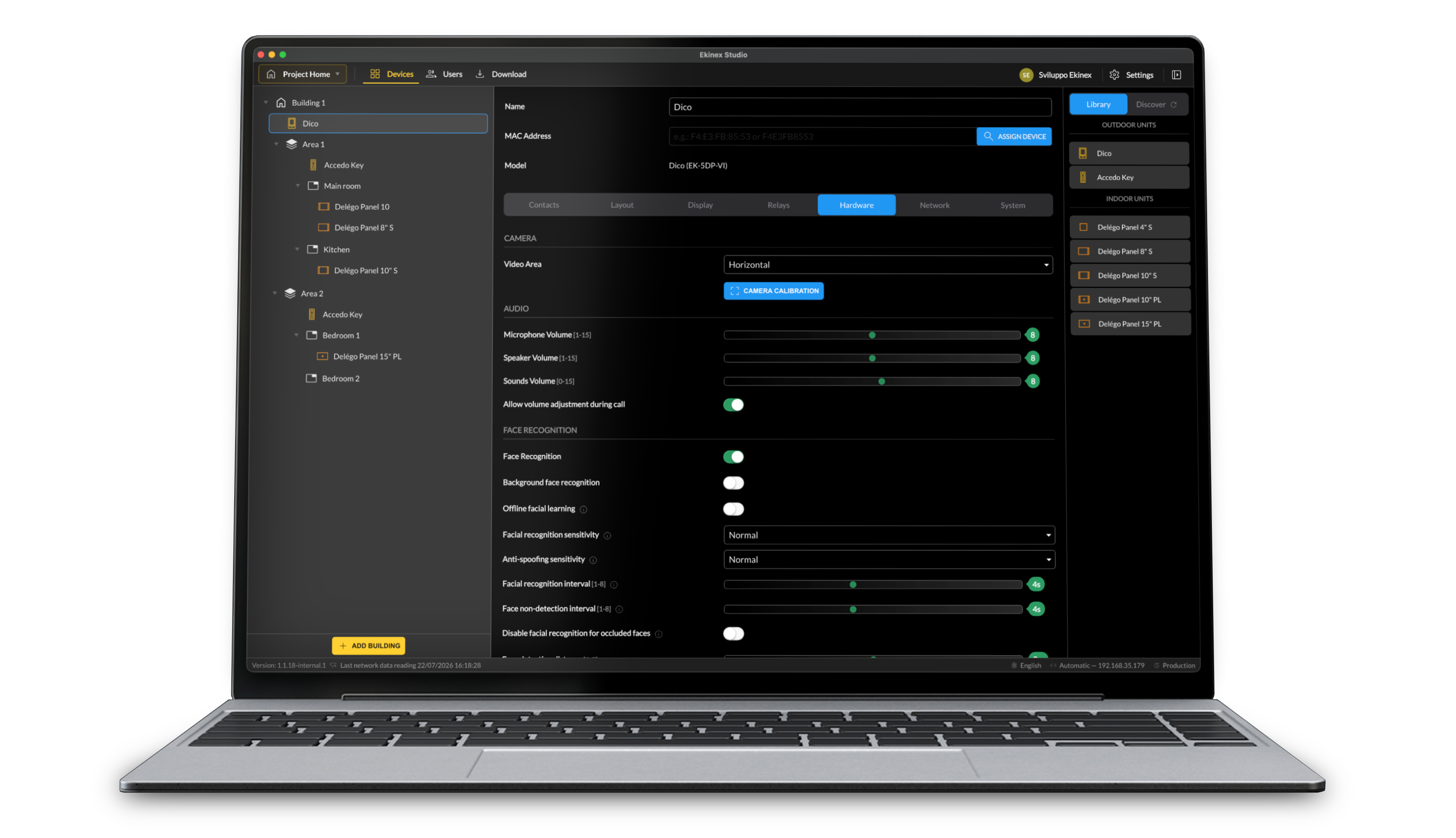
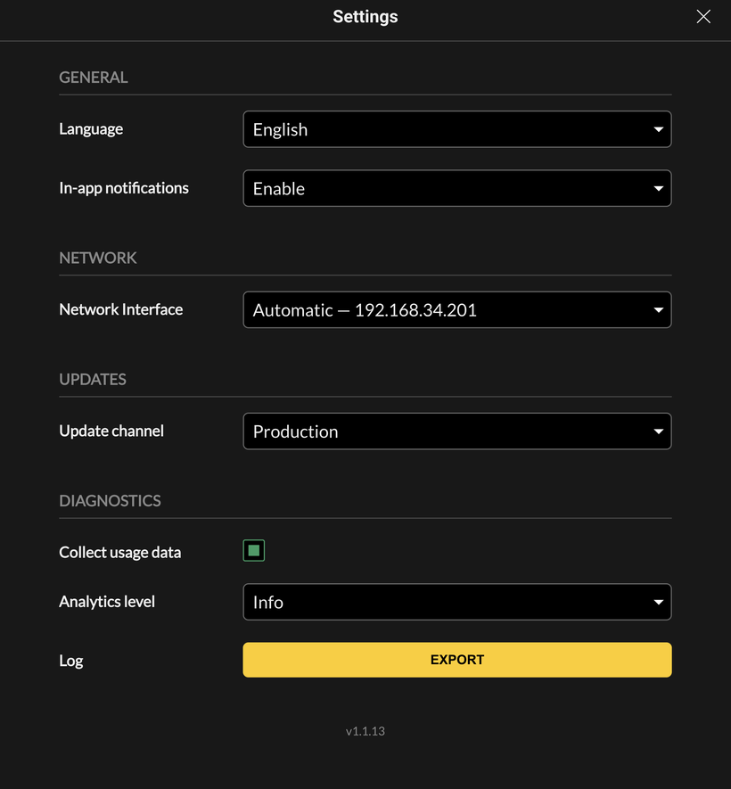
Press the Settings button on the right of the toolbar (gear symbol) to open the settings dialog. The options are organised in groups; the current software version is shown at the bottom of the dialog.
General
| Language | The language used for the software user interface (Italiano, English, Français, Deutsch, Español, Português). It can differ from the language assigned to the devices in a project. Changing it reloads the application. |
| In-app notifications | How many in-app notifications are shown: Enable (all), Alerts only, Errors only, or Disable. |
Network
| Network Interface | The computer network interface used to reach the devices. Options: Automatic (the interface preferred by the OS, whose current IP address is shown next to the option), All interfaces (search on all networks - Ethernet, Wi-Fi… - simultaneously), or a specific interface among those detected on the computer. |
Updates
| Update channel | The online distribution channel for Ekinex Studio updates: Production (default - stable public releases) or Beta (early access to features not yet publicly released). Selecting Beta requires accepting a disclaimer and is not recommended on production installations, as experimental versions may be unstable. |
Diagnostics
| Collect usage data | When enabled, Ekinex Studio collects anonymous usage and diagnostic data to help improve the software. |
| Analytics level | The detail level of the collected diagnostics: All, Info (default), Warning or Error. |
| Log - Export | Exports the local usage log to a file, for example to attach to a support request. |
System update
Ekinex Studio periodically checks for available software updates on the cloud. You can trigger a check manually with the Check for updates… menu item:
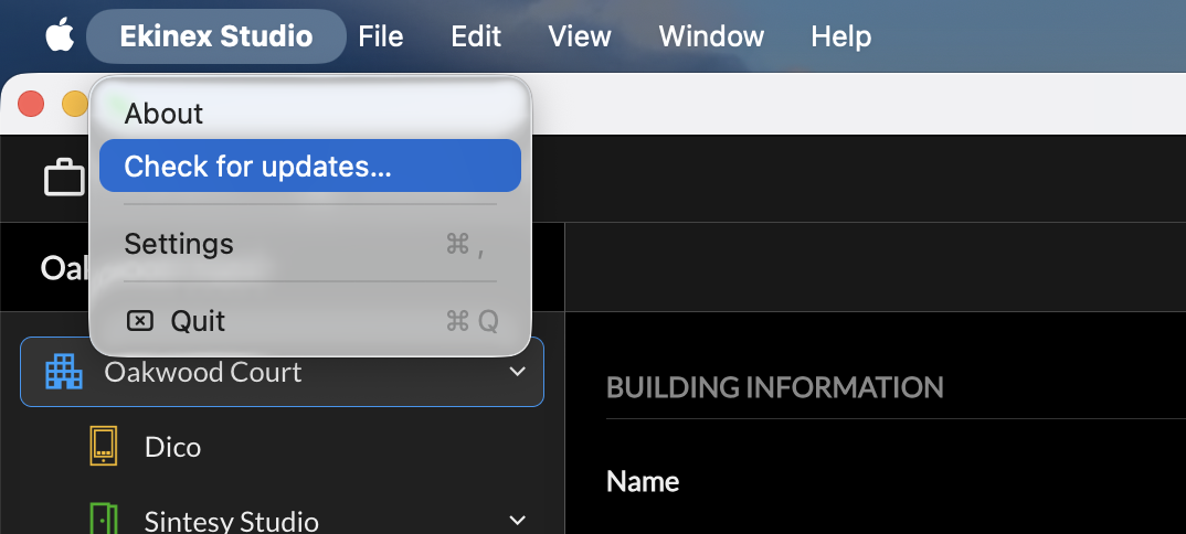
When an update is found, a red indicator in the bottom bar informs about it; press the contained link to download and apply the new version directly inside the software. The configuration is not lost or altered during the update.
Projects
Introduction
Ekinex Studio works with projects. A project contains the configuration of the intercom system of one or more buildings that need to be treated together. A project can be exported, shared and imported into another instance of Ekinex Studio; an unlimited number of projects can be created on the same computer.
New project
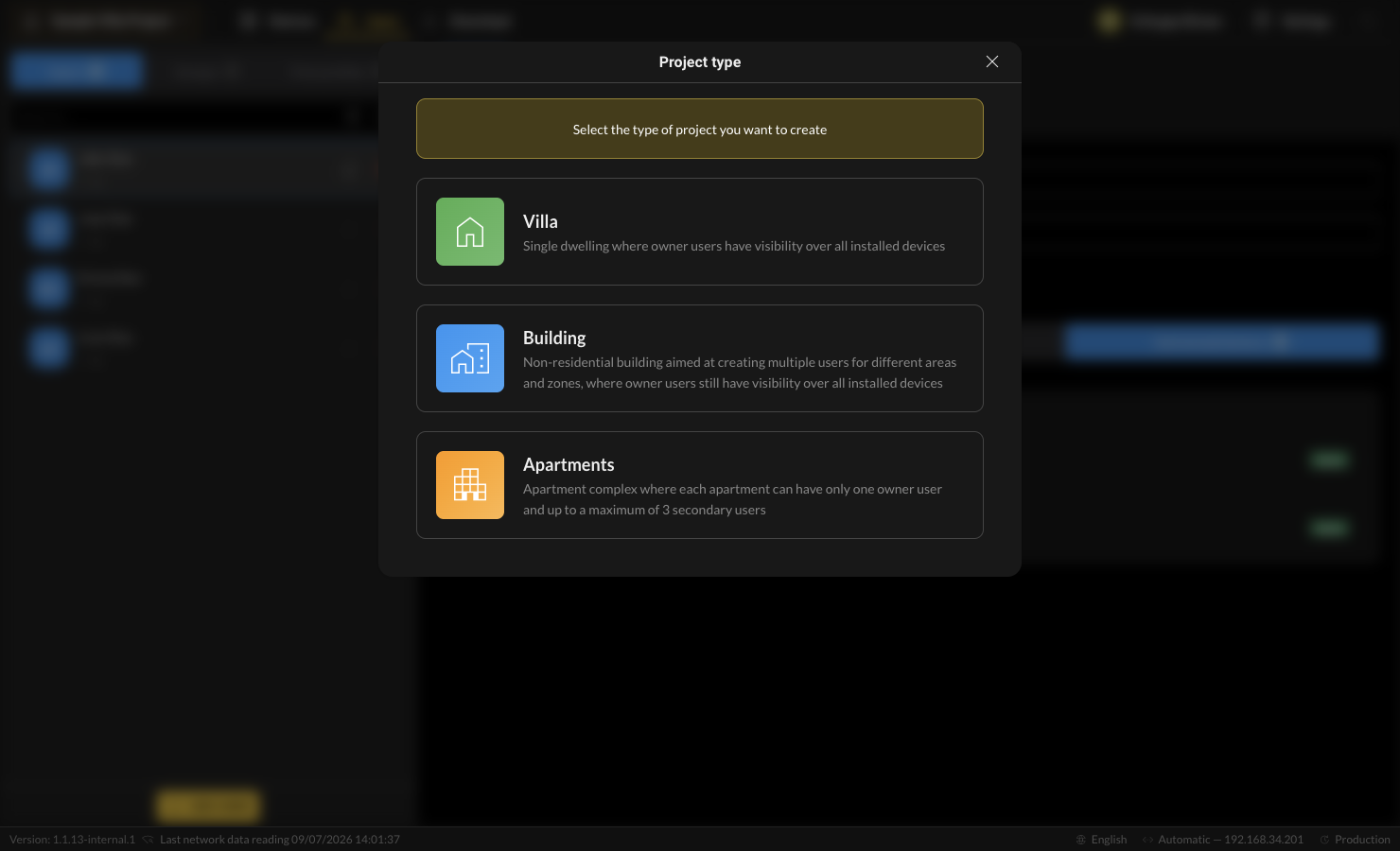
Open the project selector at the top-left of the header and press Create a new project.
| Type | Intended for | Access-management behaviour |
|---|---|---|
| Villa | Single dwelling | Owner users have visibility over all installed devices. Access is defined explicitly through groups; there is no apartment subdivision. |
| Building | Non-residential building with multiple areas / zones | Aimed at creating multiple users for different areas and zones; owner users still have visibility over all installed devices. Like Villa, every device is selectable in the access groups. |
| Apartments | Residential apartment complex | Each apartment can have one owner user and up to 3 secondary users. Users are assigned to an apartment and inherit access to its devices; access groups expose only the public (shared) devices. |
After choosing the type, the project is created with a default name that can be edited from the project selector (see Delégo Panels).
Import / export & project management
All projects are managed from the project selector in the header (top-left). It lists the Last opened project and the Other projects, and provides the create and import actions.
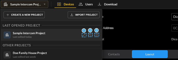
- Edit - rename the project.
- Save - export the project to a file on the computer.
- Delete - remove the project.
- Create a new project - starts the new-project flow described in Dico.
- Import project - imports a project file previously exported from this or another instance of Ekinex Studio.
- For each listed project, hovering reveals the three actions numbered in the figure above: edit, save and delete.
Buildings
Introduction
Each project is made of at least one Building, which can contain:
- one or more DICO door phone(s);
- one or more Accedo Key access-control reader(s);
- one or more Apartment(s) representing the internal spaces to be called, each containing one or more DELÉGO PANEL(s) (and, optionally, their own Accedo Key).
The following example - a project with two buildings - shows how these items are organised in the navigation tree:
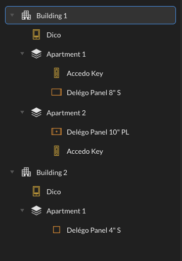
When a new project is created, the first Building with a single Apartment is automatically added to it.
Buildings
Add a new building
To add one or more Buildings to the project, press the Add building button at the bottom of the project tree column on the left:
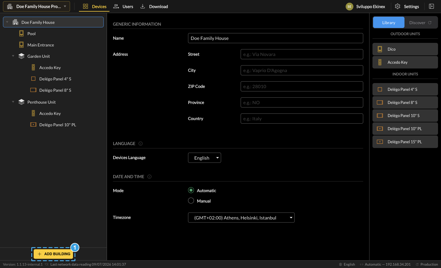
- Press Add building, at the bottom of the project tree column, to add a Building to the project.
Remove a building
A Building can be removed by pressing the corresponding bin symbol; all the contained devices are automatically removed from the project.
Building settings
Selecting a Building in the project tree lets you enter the following information, referred to the entire building and its devices:
| Address | The street address of the building: Street, City, ZIP code, Province, Country. |
| Devices language | The language used on the display of the devices belonging to the building. |
| Date and time mode | Determines whether date/time is retrieved automatically from the internet or assigned manually. |
| Timezone | The time zone of the building's region, used to determine date/time in automatic mode. |
Devices status
This tab contains the overview of all the devices associated with the Building; see the Download chapter for details.
Apartments
Add a new apartment
To add a new apartment to a Building, press the [+] button that appears when moving the cursor over it. The apartment requires:
| Name | The identifier of the apartment. |
Remove an apartment
To remove an apartment from the project, press the corresponding bin symbol; all the contained devices are automatically removed.
Third level: organising devices (Room / Zone)
Starting from v1.1, a third level can be added below the second-level node (the Apartment, in Apartments projects) to arrange its devices into sub-areas. The label of this level depends on the project type:
| Project type | Second level | Third level (new in v1.1) |
|---|---|---|
| Apartments | Apartment | Room |
| Villa | Floor | Room |
| Building | Area | Zone |
To add it, hover over a second-level node and press the [+] button, exactly as when adding an apartment.
Devices
Introduction
To add a device to the current project, drag & drop it from the right panel into the desired position in the existing Building structure. Two approaches are available:
- add a generic item from the Library and associate it with a real device later;
- Discover the available device(s) on the network and associate them directly with the project.
Library
Adding devices to the project
This section of the right panel contains all the device types that can be added to the project:
| Category | Model | Device |
|---|---|---|
| Outdoor units | EK-EK-5DP-VI | DICO door phone |
| EK-ACC-KEY-IP | Accedo Key access-control reader | |
| Indoor units | EK-DEL-4PAN-S | Delégo Panel 4" (Smart) |
| EK-DEL-8PAN-S | Delégo Panel 8" (Smart) | |
| EK-DEL-10PAN-S | Delégo Panel 10" (Smart) | |
| EK-DEL-10PAN-PL | Delégo Panel 10" (Plus) | |
| EK-DEL-15PAN-PL | Delégo Panel 15" (Plus) |
By dragging an element into the project (the DICO in a Building, the Panels in an Apartment), a generic device of the selected family is used, not yet associated with a real unit. This approach is especially helpful when preparing a project in advance (offline), when the effective installed devices are not yet available on the network.
MAC address assignment
Later, when the corresponding device is available, associate its MAC address by entering it manually or searching for it on the network:
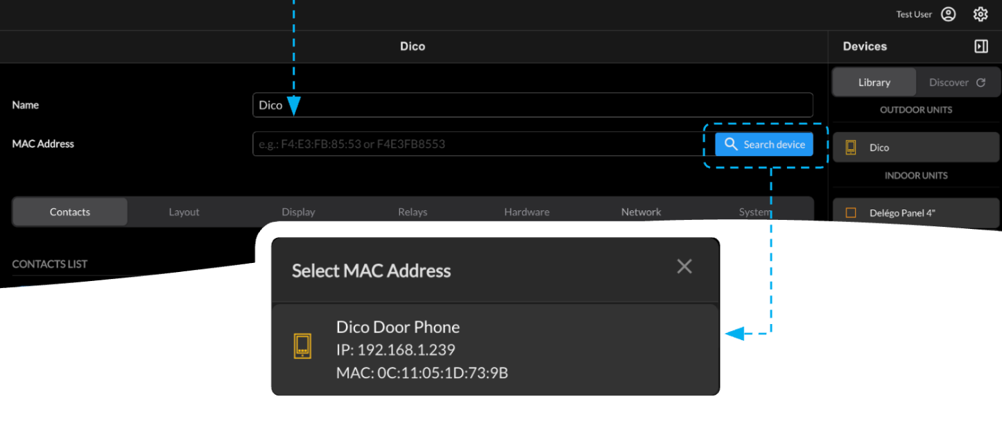
Only devices of the appropriate family that have not already been associated with the project are listed in this drop-down menu.
Manual IP assignment
If a device does not appear in the list of available MAC addresses, enter it manually by pressing the Add manually button:
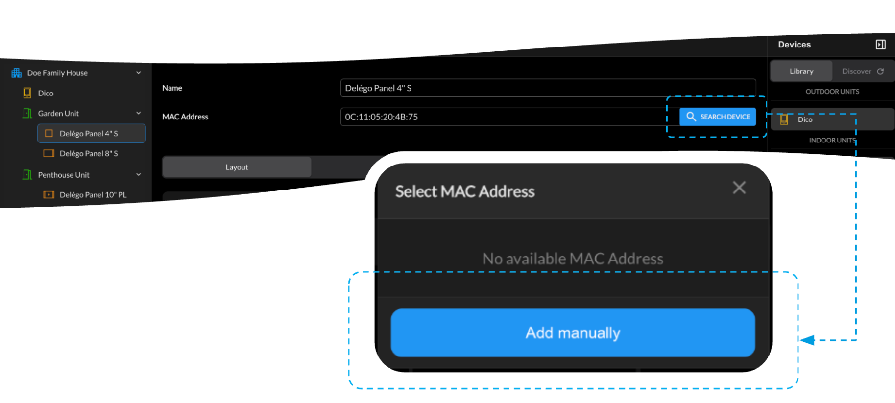
A dialog box asks for the MAC address and the actual IP address of the device.
Delégo Panel: go to the Settings area; open Device information (note the LOCAL IP) or, otherwise, Device settings › Network (note the LAN IP). When requested, enter the installer PIN (default 123456).
If the entered MAC and IP match and the device has the expected model, Ekinex Studio communicates with it exactly as if it had discovered it on the network.
Discover
This section of the right panel contains the devices detected on the network; items already associated with the project are shown in gray.
Assignment to the project
When dragging an element from Discover, it is automatically associated with the MAC address of the specific device (no later assignment is needed); in this case the firmware version of the actual device is used instead of the latest one.
If the desired device is not in the list, try one of the following:
- run the network scan again by pressing the Refresh symbol on the Discover tab title;
- change the computer's Network interface used for the scan in the Settings;
- try the manual IP assignment as explained above.
Manual update before assignment
If the device still cannot be added, it has a firmware not yet compatible with Ekinex Studio and must be upgraded first:
- Add an item of the appropriate product family from the Library.
- Select the System tab and download the latest firmware version to your computer.
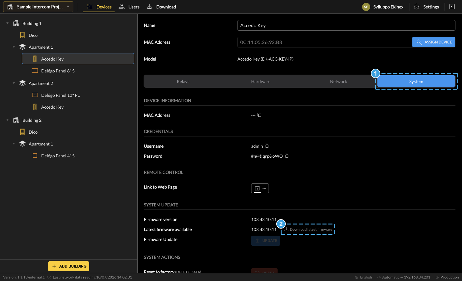
Downloading the latest firmware from the System tab. - Open the device's System tab, which shows its firmware information.
- Press Download latest firmware to fetch the newest official firmware, ready to be applied.
- Identify the device IP address (as described for manual IP assignment).
- Enter the device's IP address in a web browser and log in with the default credentials (typically admin / admin).
- Open the firmware upgrade section (Settings › Basic or Upgrade › Basic), press Upgrade, select the downloaded file and press Submit.
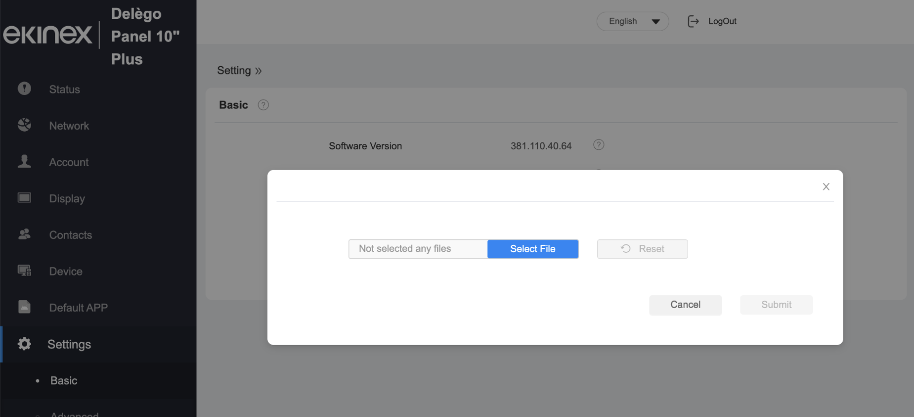
Firmware upgrade through the device web interface. - Wait for the procedure to end and run the network scan again.
Network ports for device discovery and communication
For Ekinex Studio to discover devices on the network and communicate with them, the following ports must be open on the firewall / router:
| Protocol | Port | Type | Purpose |
|---|---|---|---|
| COMMUNICATION (proprietary) | 8500 | UDP, bidirectional | Device configuration read/write (GetParam / SetParam) |
| COMMUNICATION progress | 8200 | UDP, outbound | Operation progress notification to device display |
| HTTP | 80 | TCP | Device REST API: login, config, system info, firmware/audio upload |
| HTTPS | 443 | TCP | Same as above, when device supports HTTPS |
If the client also uses Ekinex Cloud (WireGuard VPN) for remote access, or downloads firmware updates from the same network, these additional endpoints must be reachable:
| Service | Endpoint | Port |
|---|---|---|
| Ekinex Cloud auth / API | cloud.ekinex.com | TCP 443 |
| Ekinex Cloud MQTT (VPN state) | cloud.ekinex.com | TCP 8884 (WSS) |
| WireGuard tunnel | dynamic (from .conf file) | UDP, port assigned by server |
| Firmware download | www.ekinex.com | TCP 443 |
| App auto-update | www.domoticalabs.com | TCP 443 |
Passwords
When a new device is associated with the project, Ekinex Studio assigns it a securely generated password instead of the default admin. If the device is not new and a different password was previously assigned, you are asked to enter it:
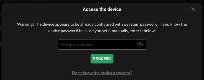
In that case the original password is used by Ekinex Studio instead of a generated one. If the original password is unknown, it can be reset from this dialog; for security reasons the device serial number (SN), printed on the back of the device, is required, along with an internet connection.
Once the device is correctly assigned, its System tab lets you copy the username and password - useful for the web interface or third-party integrations:
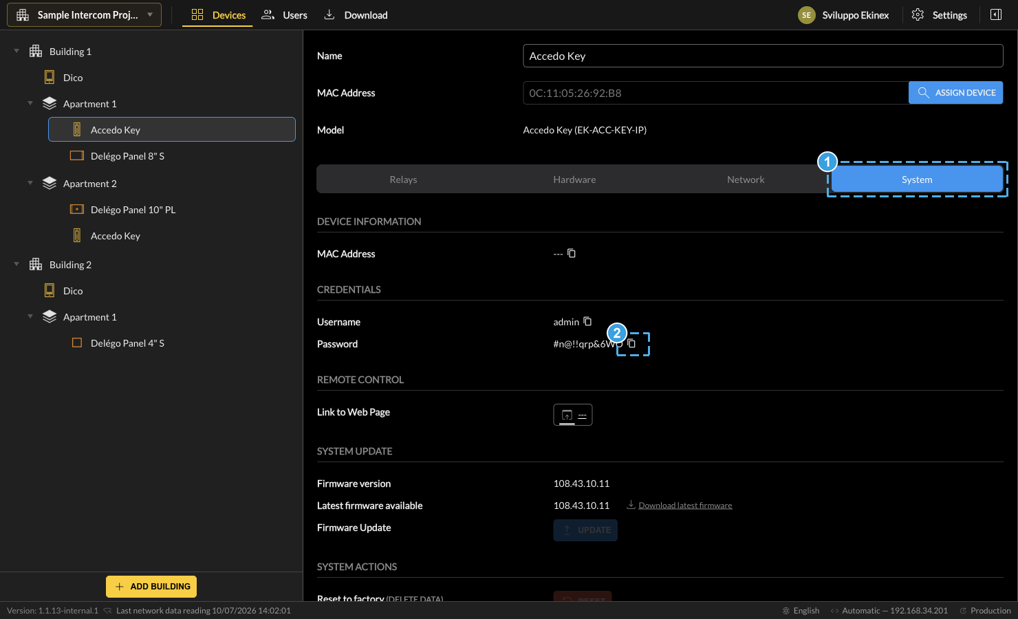
- Open the device's System tab.
- Press the copy icon next to Password to copy it to the clipboard (a confirmation message appears at the top).
Some devices, like the DICO door phone, use several passwords / PINs for different operations:
| Administrator password | Access to the device web interface. |
| HTTP API (communication) password | Sending commands to the device on the network (e.g. to open a lock). |
| PIN | Numeric code to log in on the device display. |
Each can be copied to the clipboard with its corresponding copy symbol.
Firmware update
When a device is added from Discover, its firmware version is checked for compatibility. If it is too old to be configured, you are asked to update it and the following dialog is shown:
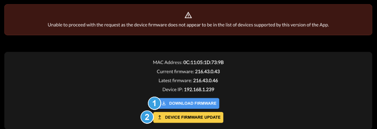
- Press Download firmware to download the latest firmware from the cloud to your computer.
- Press Device firmware update to start the update on the device using the downloaded file.
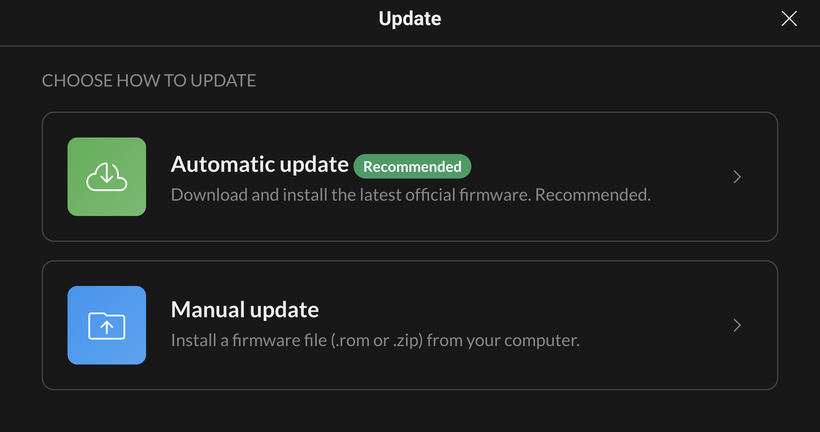
The update dialog then lets you choose how to update: Automatic - Ekinex Studio downloads and installs the latest official firmware from the cloud (recommended) - or Manual, to install a firmware .rom / .zip file from your computer.
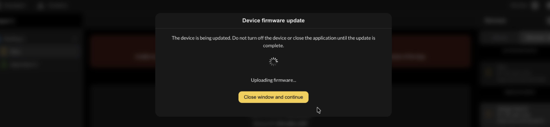
During the update, a dialog informs on the operation in progress. You can leave this window and configure other devices meanwhile; the progress dialog reappears when selecting the same device until the update completes.
When closing the dialog, Ekinex Studio refreshes the device information and, after a few seconds, the new version becomes visible in the System tab. If it does not update automatically, press Read device information at the bottom of the screen.

- Press Read device information to query the device and refresh its data (model, firmware version, reachability).
Video intercom
This chapter covers the configuration of a video-intercom system, built with DICO door phones and Delégo Panel indoor units. It opens with an overview and reading guide, then details each device.
Overview
Ekinex Studio v1.0 was dedicated exclusively to the configuration of video-intercom systems. Starting from v1.1, the software also introduces a complete access-control layer. The two domains are configured in different areas of the application, but share the same final step.
The main navigator, at the top of the window, gives access to the three working areas used throughout this manual:

| Purpose | Devices involved | Where you work |
|---|---|---|
| Video intercom | DICO door phones and Ekinex Touch (Delégo Panel) indoor units | Devices area only |
| Access control (new in v1.1) | Adds the Accedo Key reader | Devices area and the Users area |
The overview below shows a minimal video-intercom example - focusing on the project navigation tree - and points you to the specific chapters to deepen. Access control is covered separately in Access control.
This section is a reading guide: it points you to the chapters to focus on when the installation is a pure video-intercom system. Such a project is built entirely in the Devices area - a DICO door phone at the building entrance and one Ekinex Touch (Delégo Panel) inside each apartment to answer the calls:
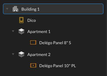
- Dico - call contacts, homepage layout, relays and audio/video hardware of the door phone.
- Delégo Panels (Ekinex Touch) - door-opening buttons and display options of the indoor units.
- Download - transfer the configuration to the physical devices.
Dico
Introduction
The DICO door phone(s) can be configured in Ekinex Studio for all intercom functionalities in the local network, by adding one or more to a Building. The configurable parameters are organized in the sections described below.
Contacts
This section defines the possible recipients of calls made by the DICO door phone; each contact can ring one or more Delégo Panel(s) and/or the smartphones of one or more users. A first contact is already available on first entry; press Add Contact to create more. Each contact requires:
| Name | The label identifying the contact. |
| Contact image | An optional picture for the calling button(s) or the DICO address book. Maximum size 300×300 pixels. |
| Devices to Call | In the Devices to Call tab, select from the building structure which Delégo Panel(s) must ring when the contact is called. |
| Users to Call | In the Users to Call tab, select which users are called on their smartphone when the contact is called (see below). |
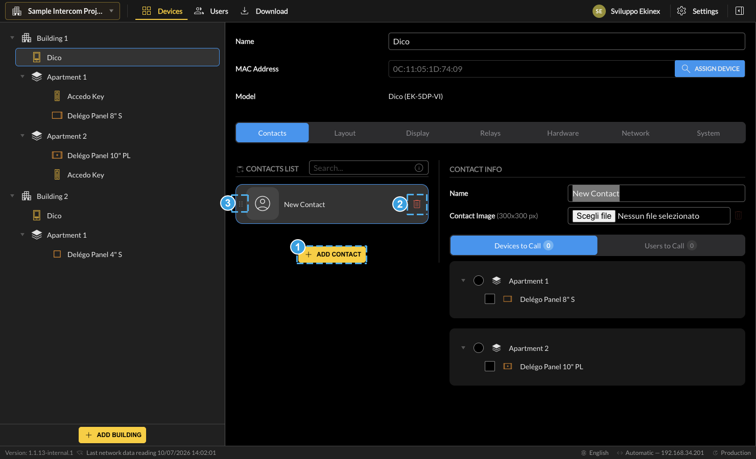
- Press Add Contact to create a new contact.
- Use the delete icon to remove the selected contact.
- Drag the handle beside the thumbnail to reorder the contacts.
Users to Call links the contact to the Users area (Users & Access Management). It lets the DICO place a call to a user on their smartphone: only users that have an Apartment Number assigned appear in this tab. The Apartment Number is set per user in Users › Edit, and becomes available once Enable Smartphone Calls is turned on for that user (see User properties). This replaces the old per-apartment smartphone setting (Add a new apartment).
Layout
This section defines the graphical aspect of the product display, and the number and functionality of the buttons. The typical homepage layout (shown when a visitor approaches, before interacting) contains:
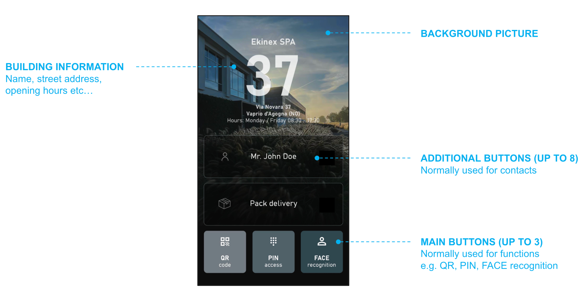
| Main buttons | Up to 3 buttons at the bottom of the display. Normally used for general functions (QR code, PIN access, face recognition), they can also call a contact. |
| Additional buttons | Up to 8 buttons organized in 4 rows along the main part of the screen. |
| Building information | Street address and number, company/family name and additional info (e.g. opening hours) shown in the upper part, if space allows. |
| Background picture | Customizable background image. |
Each row of additional buttons can host two half-width buttons or a single extended button; numbering starts from the bottom row (closest to the main buttons) upward:
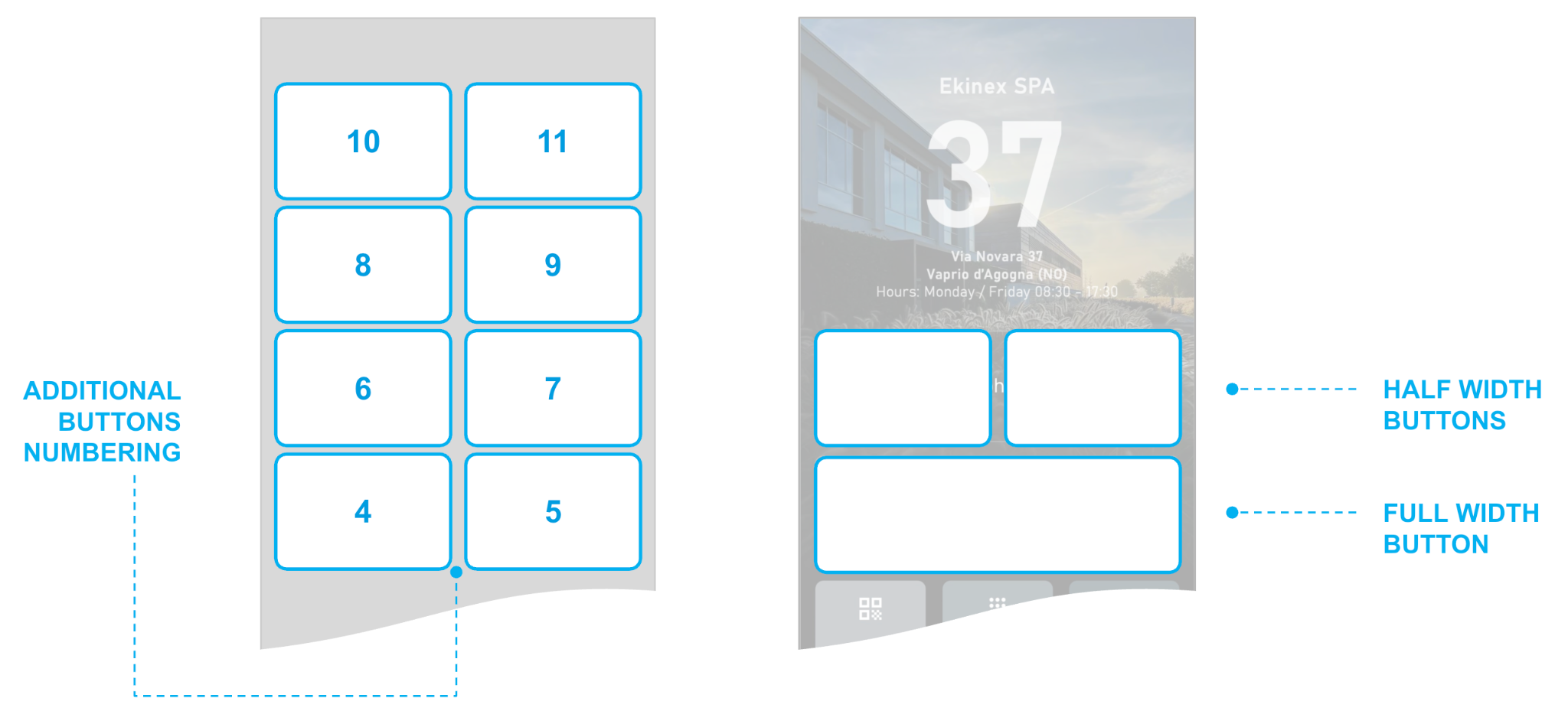
The first element in the DICO Layout tab lets you choose the preferred layout, which determines the number of available buttons:
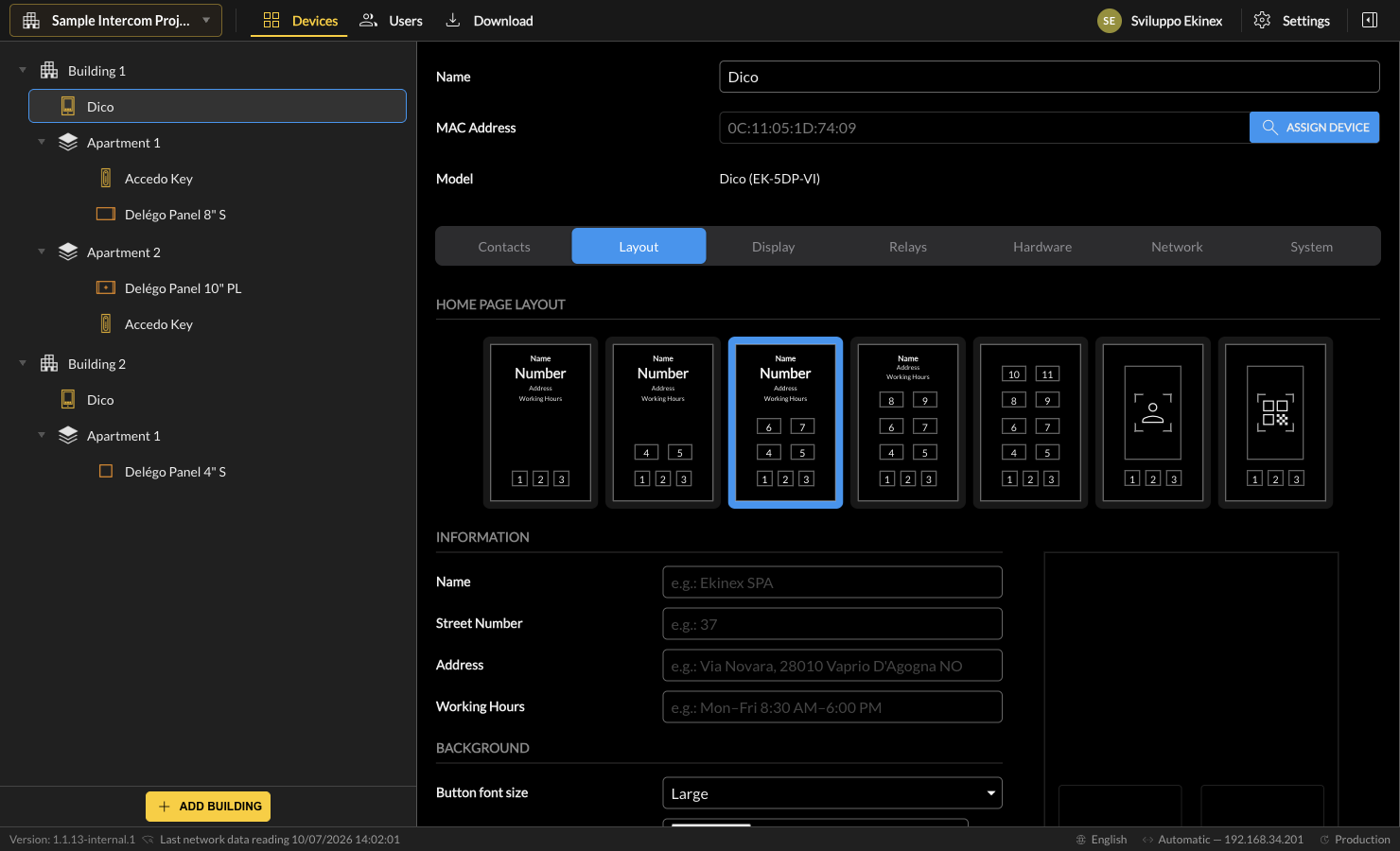
The following additional data can be set before customizing the buttons:
| Name / Street number / Address / Working hours | Building address information shown in the header. |
| Button font size | Size of the labels inside the buttons. |
| Background image | Picture placed on the homepage background. Maximum (and suggested) size 900×1600 pixels. |
For each button row you can enable one or more buttons; they adapt their width automatically. Each button is customized with:
| Type | The button function: Contact (calls a set contact), QR code (reads a QR with the front camera), PIN code (shows the numeric keypad), Face recognition (identifies an enrolled face), Tenants list (shows the full address book), Free text (a custom label), HTTP command (sends an HTTP string, e.g. to switch a KNX light through a Delégo Server). |
| Name | The label displayed in the button. |
| Icon | The graphical symbol inside the button. For contact buttons, selecting Contact picture uses the contact's image. |
| Color | The background colour of the button. |
| Opacity | The degree of transparency of the button against the background colour. |
The preview shows in advance the graphical result on the display after the download.
Display
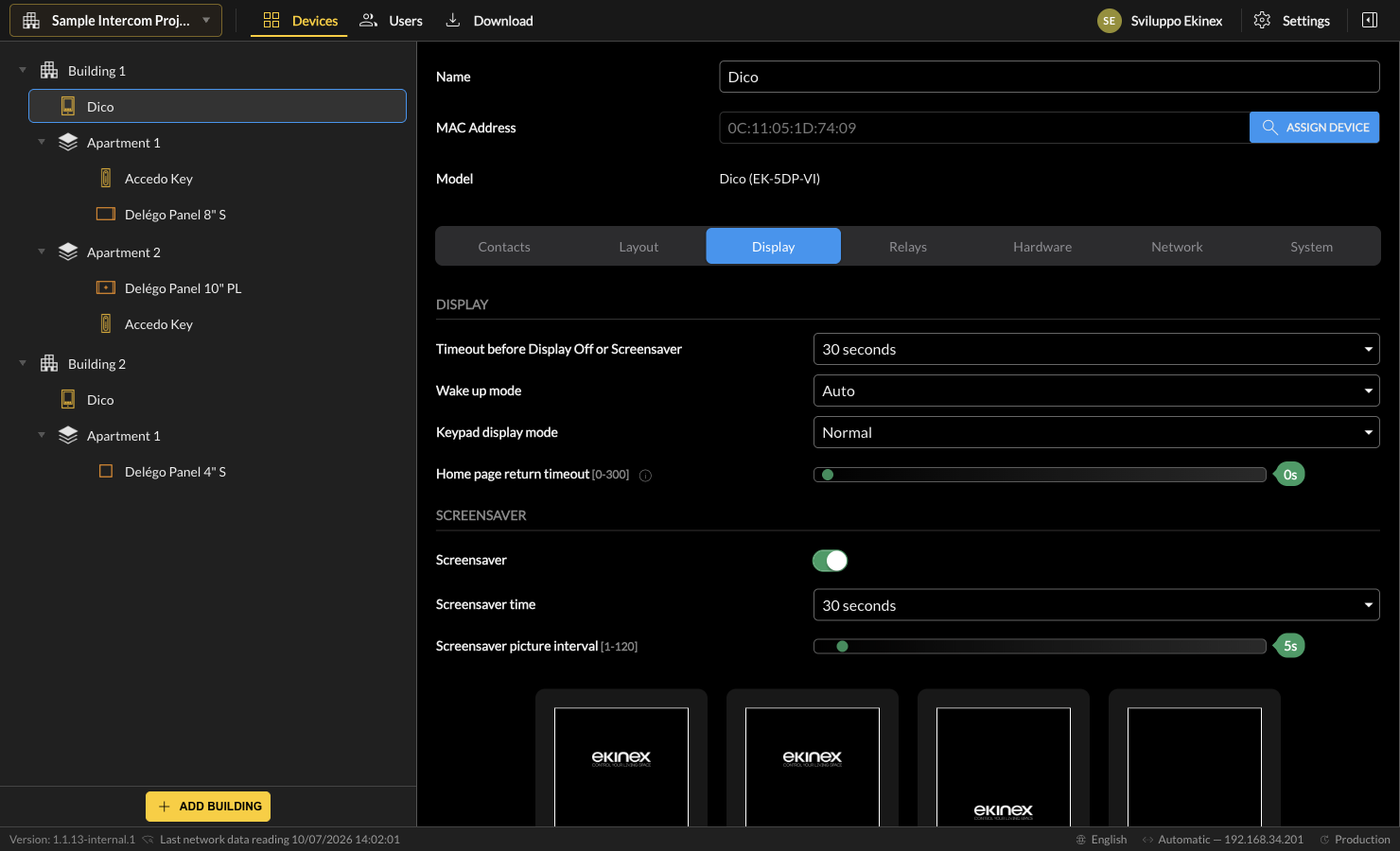
The general aspect of the display is set with:
| Timeout before display off or screensaver | Inactivity timeout for the automatic switch-off (or screensaver) of the display (from 5 seconds to 30 minutes). |
| Wake up mode | Switch-on strategy: Manual (press on the display), Auto (proximity sensor), or Touch-here icon. |
| Keypad display mode | Order of the numeric keys. The Random option places numbers in casual order for higher security. |
| Home page return timeout | Seconds before automatic return to the homepage after a visitor opens a different section (0–300). |
The following options refer to the screensaver:
| Screensaver | Enables the screensaver. |
| Screensaver time | Inactivity timeout before the screensaver activates. |
| Screensaver picture interval | Seconds between two consecutive images. |
To change the default screensaver pictures, delete them with the bin and press [+] to browse for a new one:
Relays
Internal relay
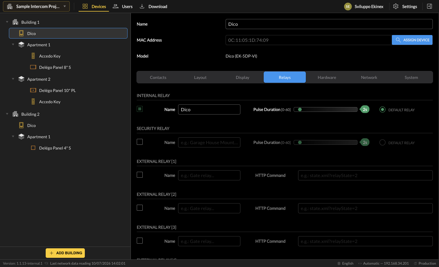
If the internal relay opens a door, enable it with the corresponding checkbox; the following parameters can be set:
| Name | Label identifying the door opened by the relay. |
| Pulse duration | Seconds of activation of the relay. |
| Default relay | Select if the internal relay is the default for the DICO door phone. |
Security relay
A secondary lock can be commanded by connecting a security relay to the RS485 port of DICO. The same settings seen for the internal relay are available.
External relays
DICO can open up to 4 external relays by sending HTTP commands on the local network:
| Enable flag | Enable this checkbox to use the relay. |
| Name | Label identifying the door opened by the relay. |
| HTTP command | The HTTP URL called when the relay is triggered. |
Commands with Delégo Server
The external relays of DICO can send a command to a Delégo Server, for example to trigger a KNX actuator. Compose the HTTP command as follows. Open the Delégo Server web interface in the administration space and activate Expert mode in the toolbar:

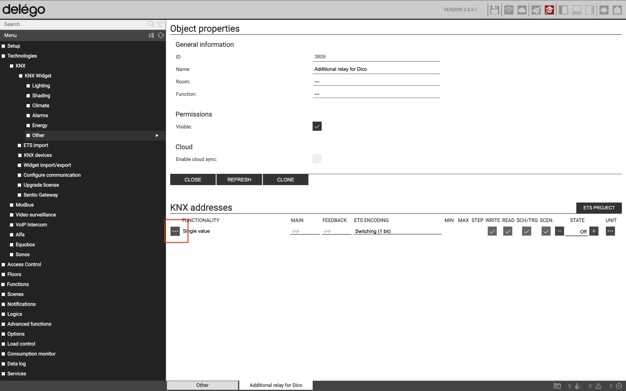
For KNX commands, if you do not yet have a widget containing the group address to command, create one:
- Select Technologies › KNX › KNX Widgets › Other and open the page.
- Select Single value in the drop-down to the left of the Add button.
- Press Add, wait for the new entry and open it with the edit button.
- On the Single value line, in the KNX addresses section, enter the group address in the Main field and any feedback in the Feedback field (or drag them from the ETS project tree).
- If you do not want this widget in the supervision, do not select any Room or Function.
If the widget already exists, open its detail sheet, locate the group address entry in the KNX addresses section and open its detail; the object ID is the first entry in the details section:
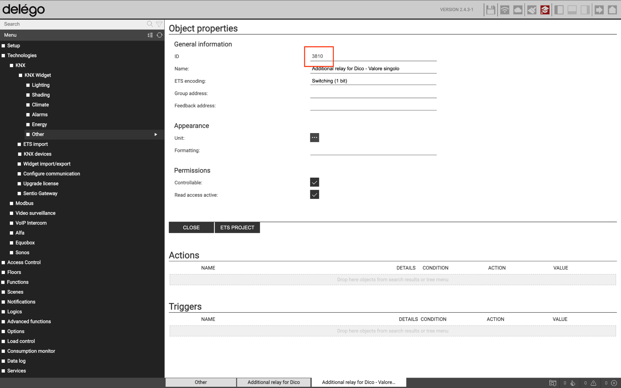
For MODBUS widgets, proceed similarly, identifying the sub-object corresponding to the register to control and detecting its ID. Once the object ID is known, compose the command string as follows:
http://<IP>/www/modules/system/soapwrapper.php?format=json&username=<user>&password=<pwd>&function=runonelement&id=<id>&action=<action>&payload=<payload>
| IP address | Delégo Server IP address. |
| username / password | Valid credentials of a local Delégo Server user. |
| id | ID of the previously identified object. |
| action | Depends on the object type: SETVALUE (KNX or MODBUS commands) or EXECUTE (Delégo scenarios). |
| payload | For SETVALUE actions, the numeric value to send to the object (e.g. 1 for an ON command on the KNX bus). |
Hardware
Camera
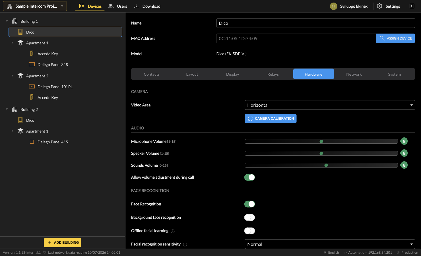
| Video area | Orientation of the video stream: horizontal or vertical. |
| Calibration | Opens a popup to set, for a horizontal stream, the height of the camera image to be streamed. |
Audio
| Microphone / Speaker / Sounds volume | Volume level for the corresponding audio element. |
| Allow volume adjustment during call | If enabled, visitors can calibrate the audio volume during the call from the DICO display. |
Face recognition
| Face recognition | Enables face-recognition access on the door phone. |
| Background face recognition | If enabled, face recognition runs continuously in the background without showing the front camera; no message is displayed unless a valid face is detected. |
| Offline facial learning | Allows enrolling faces directly on the device, without a cloud connection. |
| Facial recognition sensitivity | Recognition threshold: Low / Normal / High / Very high. |
| Anti-spoofing sensitivity | Strictness of the liveness / anti-spoofing check: Normal / High / Very high. |
| Facial recognition interval | Minimum interval between two consecutive recognitions (1–8). |
White light
| Mode | Whether the white LED on top of DICO (to highlight visitors in low light) is activated by the motion sensor (Automatic) or Off. |
| Brightness | Intensity of the LED if enabled. |
Tamper alarm
| Enabled | If selected, the internal sensor is activated and a sound alarm plays in case of tampering. |
Network
This section assigns the desired IP addressing to the DICO door phone:
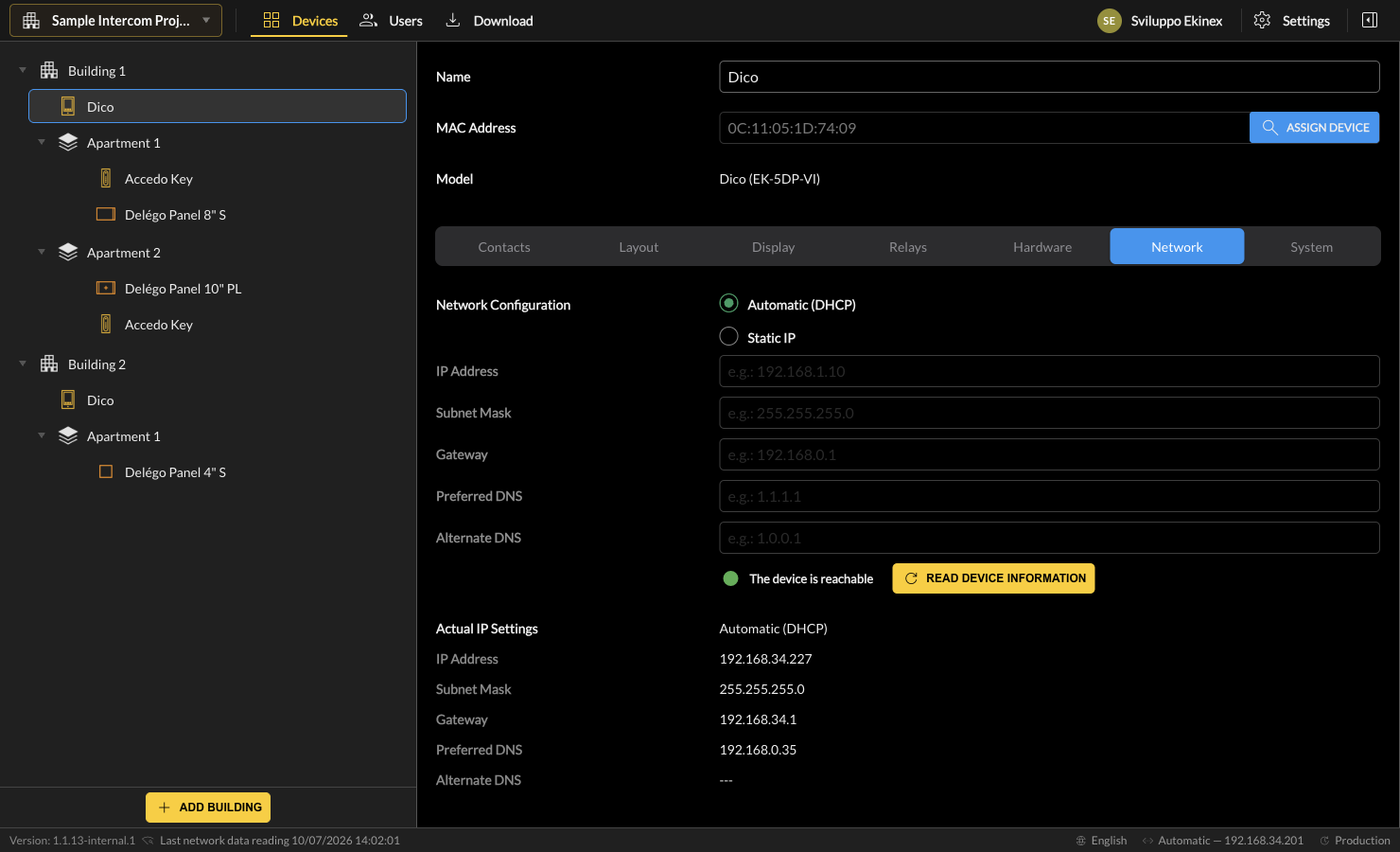
| Network configuration | Whether the IP address is obtained automatically (DHCP) or assigned statically. |
| IP address / Subnet mask / Gateway / Preferred DNS / Alternate DNS | The IP address components, to be assigned in case of static IP. |
The bottom of the screen reports the actual IP address of the device (if associated with a MAC address and reachable); it can differ from the desired configuration until a Download is performed.
System
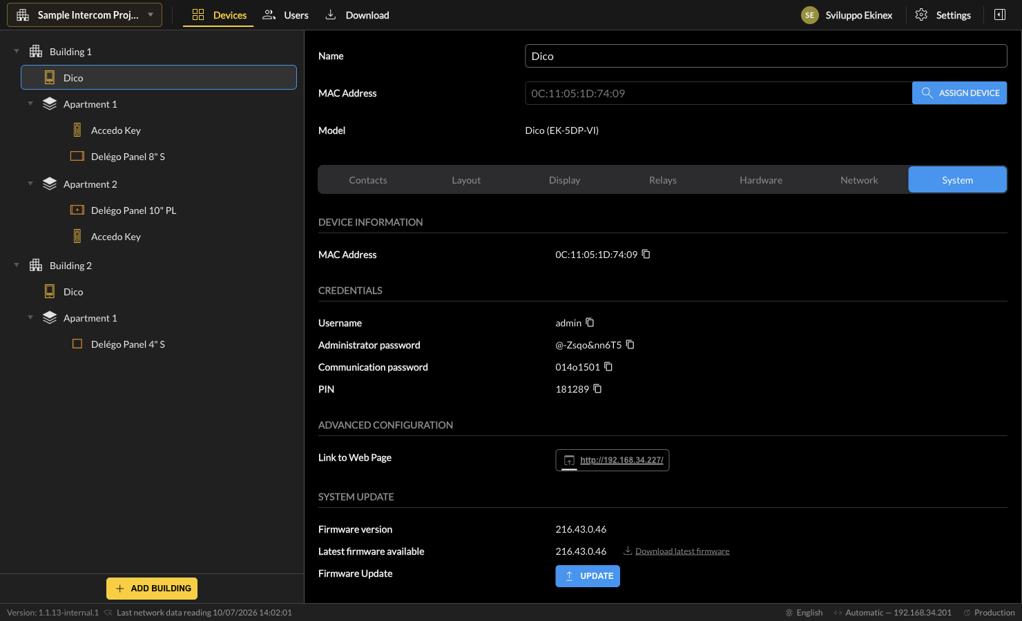
This tab contains information read from the device (if a MAC address has been entered).
Device information
| Model | The part number of the device. |
| MAC address | The MAC address of the device. |
Credentials
| Username | User to access the web interface. |
| Administrator password | Password to access the web interface. |
| Communication (HTTP) password | Password for HTTP commands to the DICO door phone. |
| PIN | Numeric PIN to access the settings on the display. |
Advanced configuration
| Link to web page | Opens the DICO web interface for advanced settings not managed by Ekinex Studio. |
System update
| Firmware version | Firmware detected on the connected device. |
| Latest firmware available | Most updated version on the cloud; the link downloads it to your computer. |
| Firmware update | Starts the update procedure (see Firmware update). |
System actions & reachability
| Reset to factory | Clears all settings and returns the device to factory defaults. |
| Reboot | Restarts the device without other modifications. |
| Read device information | Requests updated information from the device. |
Delégo Panels
Introduction
The Delégo Panels can be configured in Ekinex Studio for all intercom functionalities, by adding one or more to an Apartment. The configurable parameters are organized in the sections below.
Layout
This section configures up to three buttons, shown during the preview and video call, to open doors or gates:
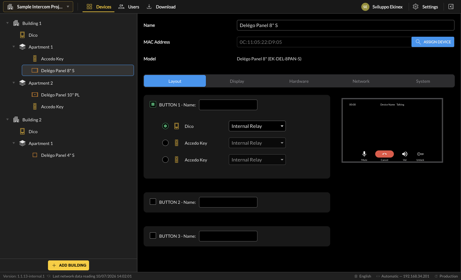
| Enable | Select the checkbox to enable the button on the display. |
| Name | The label associated with the button on the display. |
| Device / Relay | Among the devices offering one or more relays, select which is opened when the button is pressed. |
A preview of the final result is shown on the right; the actual result may differ slightly depending on the panel model.
Display
Display
| Auto brightness | Automatic adaptation of the display luminosity. |
| Brightness level | Manual adjustment of the brightness. |
Motion
| Proximity sensor | Enables the motion sensor to switch on the display. |
| Proximity detection distance | Short or long detection distance. |
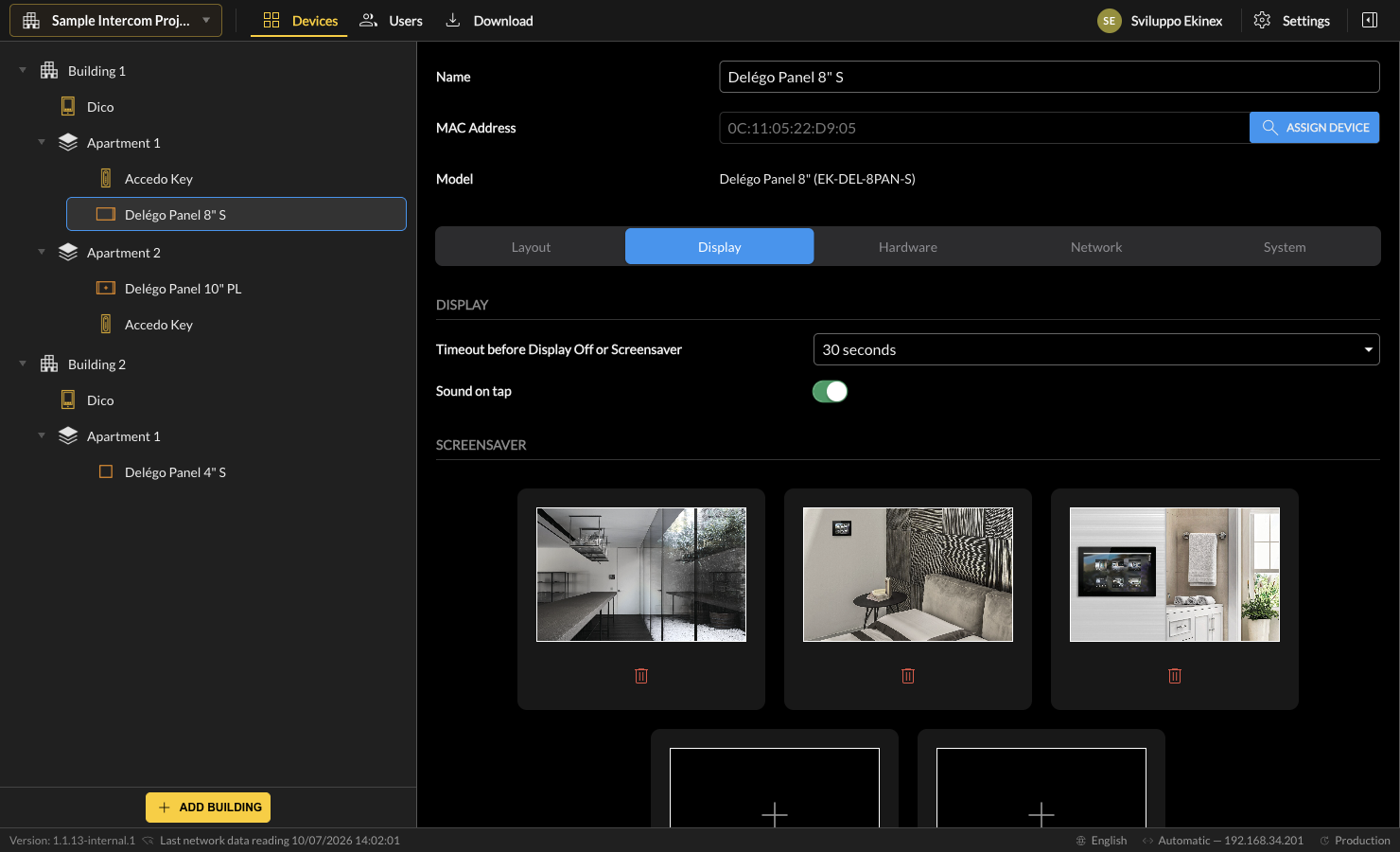
Screensaver
| Screensaver | Enables or disables the screensaver on the display. |
To change the default screensaver pictures, delete them with the bin and press [+] to browse for a new one:
Hardware
This section is available only on certain panel models; on the models that expose it, it offers:
Internal relay
| Enable | Enable the relay so it can be associated with a button on the display (of the same or another panel). |
| Name | Label identifying the relay. |
| Pulse duration | Seconds for the relay triggering. |
Volume
| Ringtone / Call / Microphone / Media volume | Volume level for the corresponding audio element. |
Network
This section assigns the desired IP addressing to the Delégo Panel:
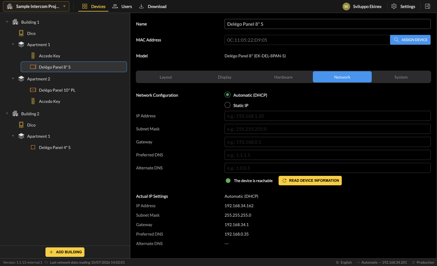
| Network configuration | Whether the IP address is obtained automatically (DHCP) or assigned statically. |
| IP address / Subnet mask / Gateway / Preferred DNS / Alternate DNS | The IP address components, to be assigned in case of static IP. |
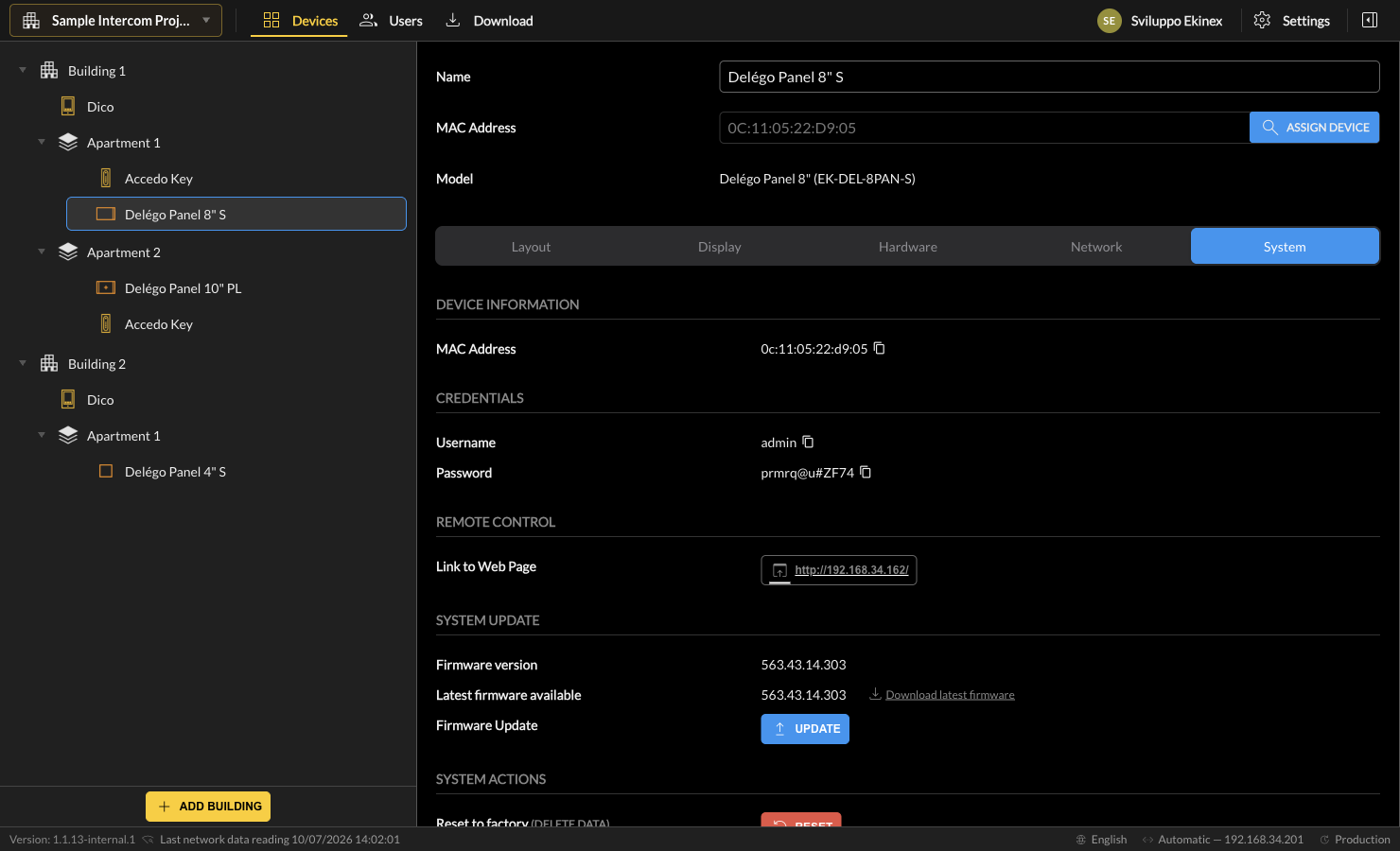
System
This tab contains information read from the device (if a MAC address has been entered): Device information (Model, MAC address), Credentials (Username, Password), Remote control (link to the web page), System update (firmware version, latest available, update button), and System actions (Reset to factory, Reboot, Read device information). The behaviour is the same as described for the DICO in System.
Access control
This chapter covers access control, introduced in v1.1 with the Accedo Key reader and the Users area. It opens with an overview, then details the reader and the full user / access-management workflow.
Overview
This section is the reading guide for when, besides video intercom, the installation also requires access control. On top of the video-intercom project you add one or more Accedo Key readers - typically one inside each apartment (and, optionally, one at a shared entrance). The navigation tree then also contains the readers:
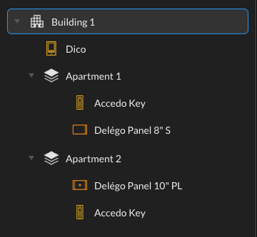
- Accedo Key - configuration of the access reader in the Devices area.
- Users & Access Management - who may open which reader and when (users, groups, time profiles, credentials).
Accedo Key
Introduction
The Accedo Key (EK-ACC-KEY-IP) is an IP access-control reader that opens doors and gates by PIN code, QR code or RFID card. As described in the Buildings section (Buildings), it can be added either directly under a Building - to control a shared / common entrance - or inside an Apartment / zone, to control that unit's own access.
The configurable parameters are organized in the sections described below.
Relays
The Accedo Key can command locks both through its own relays and through HTTP commands sent on the network, and it can trigger custom actions in response to access events.
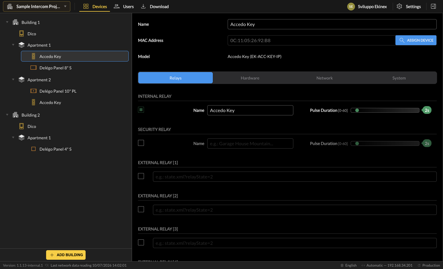
| Internal relay | The on-board relay. Set a Name (label of the door) and a Pulse duration (0–60 s). |
| Security relay | A secondary lock connected to the RS485 port, with the same Name and Pulse duration options. |
| External relay [1…4] | Up to 4 external relays commanded via HTTP on the local network (for example a KNX actuator through a Delégo Server - see Commands with Delégo Server). |
| Action URL | HTTP URLs called automatically on specific access events: valid QR code, invalid QR code and valid code entered. |
Hardware
This section sets the physical feedback of the reader:
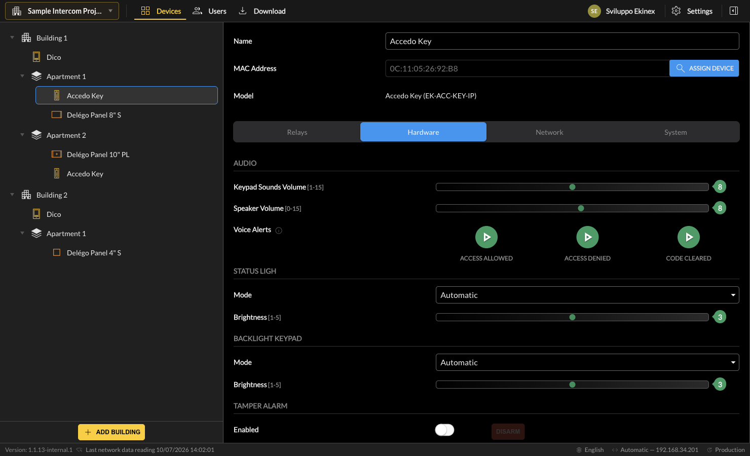
Audio
| Keypad sounds volume | Volume of the keypad feedback tones (1–15). |
| Speaker volume | Volume of the speaker (0–15). |
| Voice alerts | Spoken confirmations for Access allowed, Access denied and Code cleared (each can be previewed). |
Status light & backlight
| Status light | Mode (Off / Automatic) and Brightness (1–5). |
| Backlight keypad | Mode (Automatic / On) and Brightness (1–5). |
Tamper alarm
| Enabled | Activates the internal tamper sensor; the alarm can be disarmed when needed. |
Network
This section assigns the desired IP addressing to the Accedo Key:
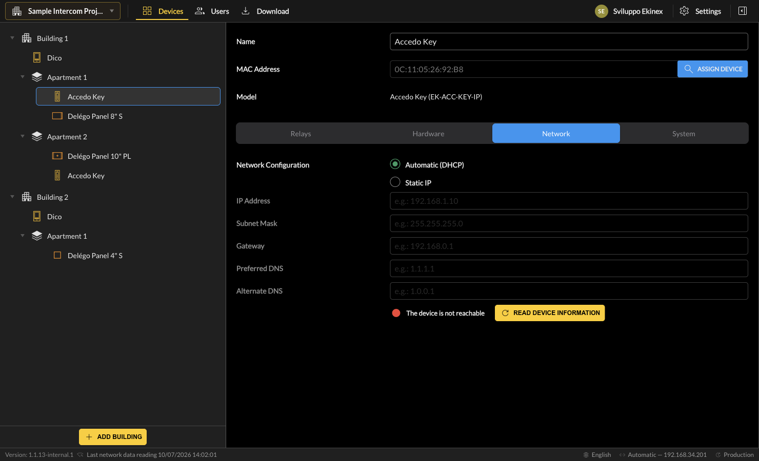
| Network configuration | Whether the IP address is obtained automatically (DHCP) or assigned statically. |
| IP address / Subnet mask / Gateway / Preferred DNS / Alternate DNS | The IP address components, to be assigned in case of static IP. |
The bottom of the section reports the connection status and offers the Read device information action.
System
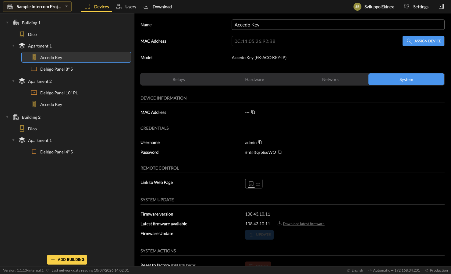
This tab contains information read from the device (if a MAC address has been entered): Device information (MAC address), Credentials (Username, Password), Remote control (Link to web page), System update (firmware version, latest available, update button) and System actions.
Users & Access Management
This chapter covers the configuration of users, access groups and time profiles - the access-control area of Ekinex Studio, reached from the Users entry in the application header.
Introduction
The Users area is the section of Ekinex Studio dedicated to access control: it defines who may operate the intercom and access-control devices of a project, on which devices, and when. It is reached from the Users entry in the application header.
The area is organised into three subsections, selectable from the tabs at the top of the left panel:
- Users - the individual people (residents, staff, guests) who are granted access.
- Groups - named sets of users that share the same device permissions and schedules.
- Time profiles - the schedules that determine the time windows during which access is granted.

Access management model
Access is never granted directly from a user to a device. It is the result of the combination of the three subsections:
- the user belongs to a group;
- that group authorises the device;
- the current moment falls inside one of the group's active time profiles.
A newly created group is automatically associated with the system time profile Always (00:00–23:59, every day), so that access is granted at all times until a more restrictive schedule is applied.
| Entity | Answers the question | Key relationships |
|---|---|---|
| User | Who? | Belongs to one or more Groups; (Apartments projects) is assigned to an Apartment. |
| Group | What? (which devices) | Contains Users; authorises Devices; uses Time profiles. |
| Time profile | When? | Associated with one or more Groups. |
The Users subsection
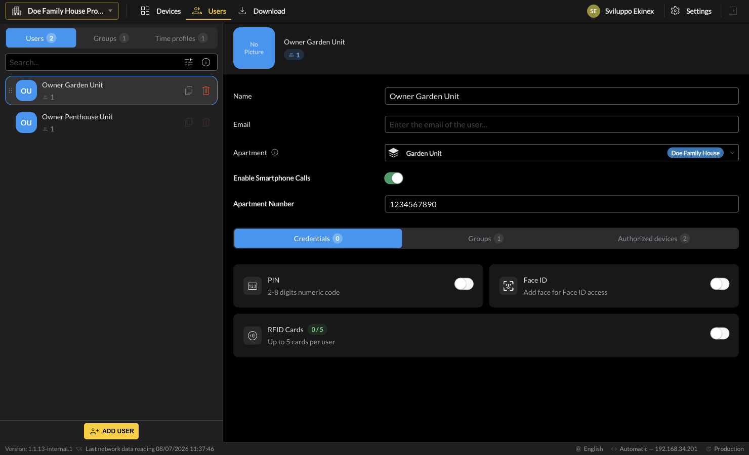
The Users subsection lists every person defined in the project. Select a user in the left list to edit its properties on the right, or click ADD USER to create a new one. The search field at the top of the list filters users by name.
User properties
The upper part of the detail panel holds the identity and, in Apartments-type projects, the apartment association of the user.
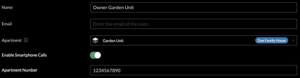
| Field | Description |
|---|---|
| Name | Display name of the user. |
| Optional e-mail address of the user. | |
| Apartment | Apartments-type projects only. The apartment the user belongs to. The user inherits access to every device located in that apartment (see Project types: Apartments vs Villa / Building). |
| Enable Smartphone Calls | Enables forwarding of intercom calls to the user's smartphone. |
| Apartment Number | The dialing / directory number associated with the user's apartment. |
Credentials
The Credentials tab defines how the user physically authenticates at a device.
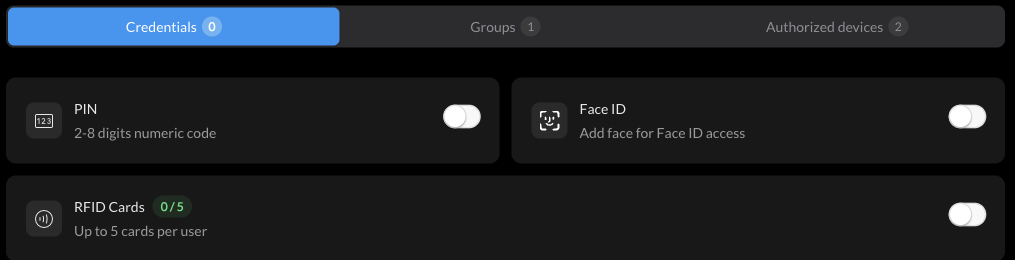
- PIN - a 2 to 8 digit numeric code.
- Face ID - face enrolment for facial-recognition access.
- RFID Cards - up to 5 RFID cards per user.
Group membership
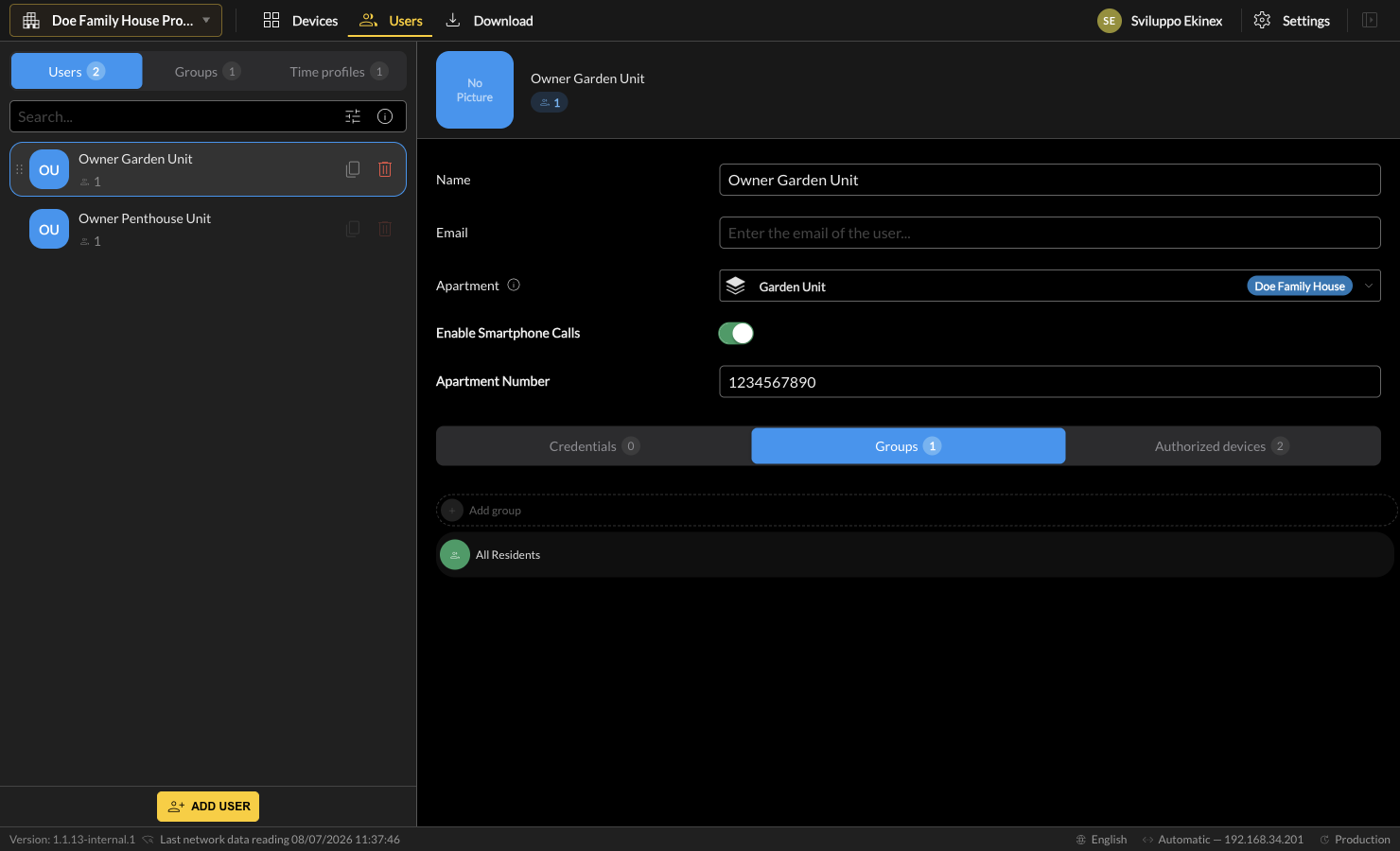
The Groups tab of a user shows the groups the user belongs to. Use Add group to add the user to further groups.
Authorized devices
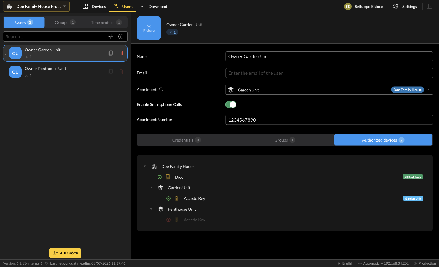
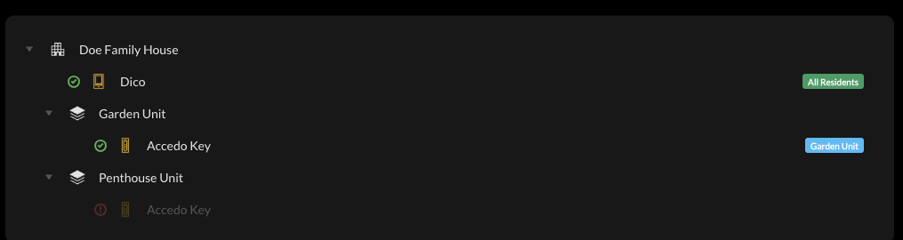
The Authorized devices tab is a read-only summary of the devices the user can actually operate, computed from all the mechanisms described in this chapter. Each entry carries a tag that explains why access is granted.
The Groups subsection
A Group ties together a set of users, a set of authorised devices and one or more time profiles. Groups are the central mechanism for granting access to shared / public devices. Each group has a Name, an optional Description and a Color used for its tags throughout the interface.
The group detail is organised in three tabs:
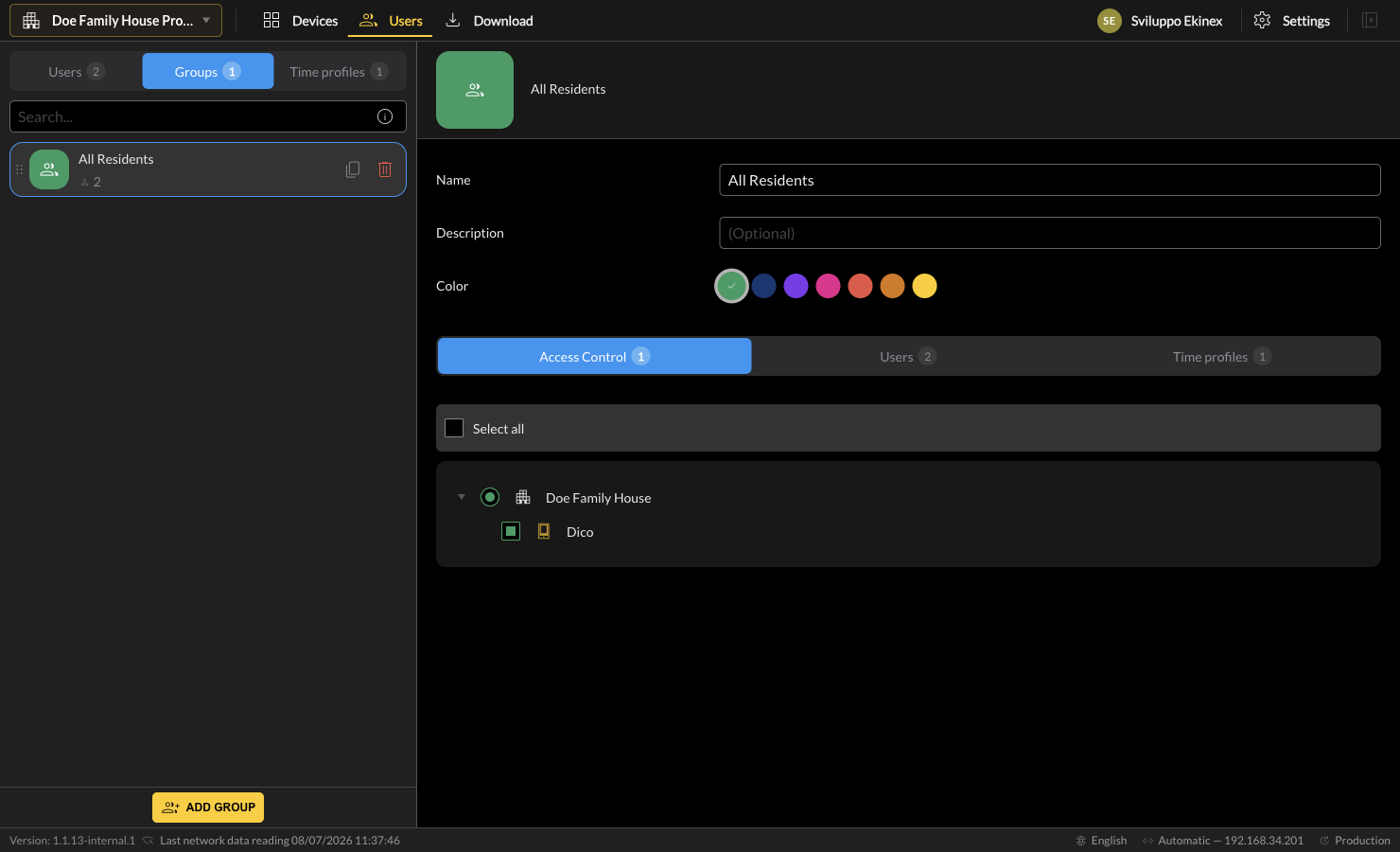
Access Control
Selects the devices the group authorises, presented as the project's device tree. Use the checkboxes (or Select all) to grant access.
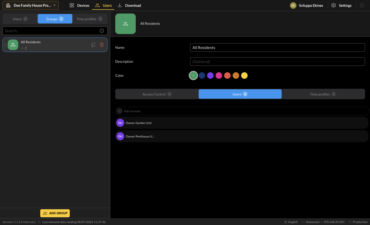
Users (members)
Lists the members of the group. Use Add member to add users.
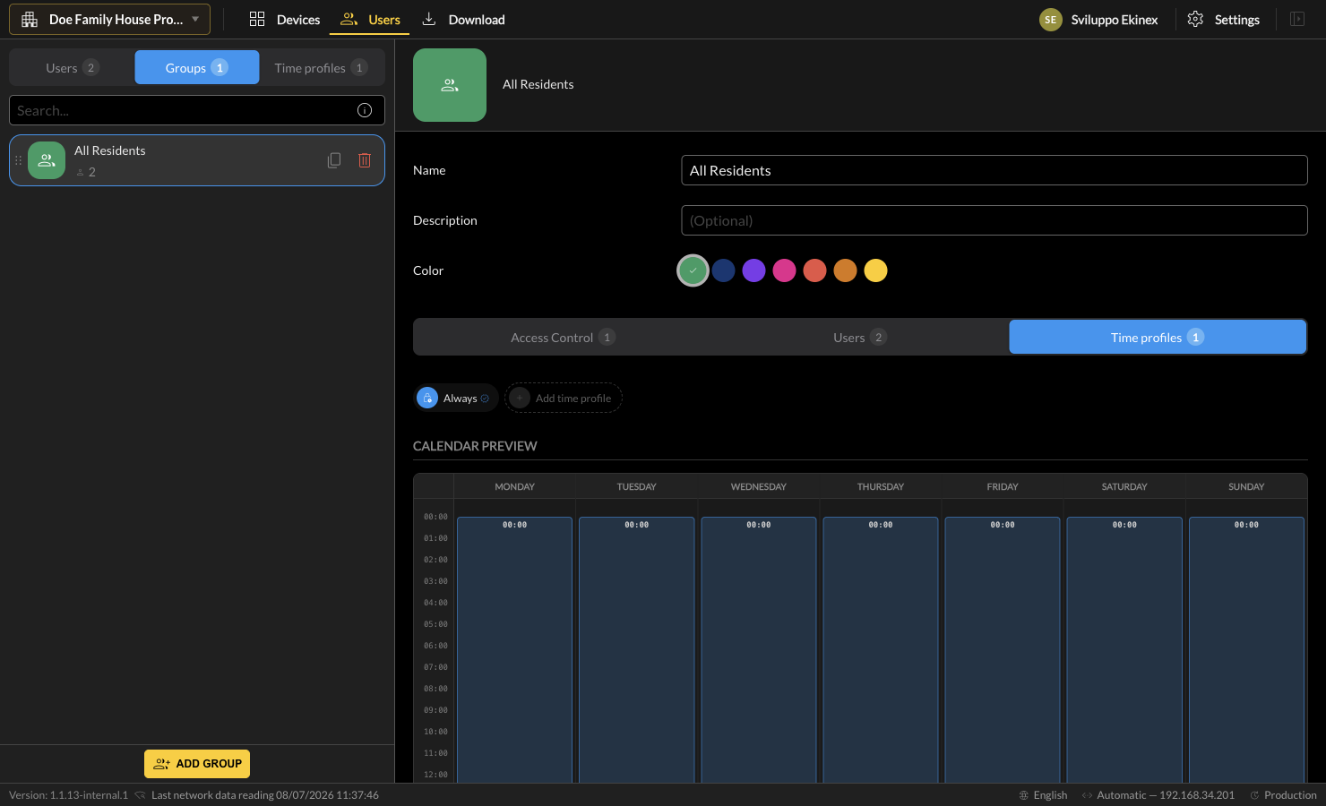
Time profiles
Associates the group with one or more time profiles and shows a Calendar Preview of the resulting weekly access window. A group with no active schedule denies access to its devices.
The Time profiles subsection
A Time profile defines the time windows during which the groups that use it grant access. Select a profile to edit it, or click ADD TIME PROFILE to create one.
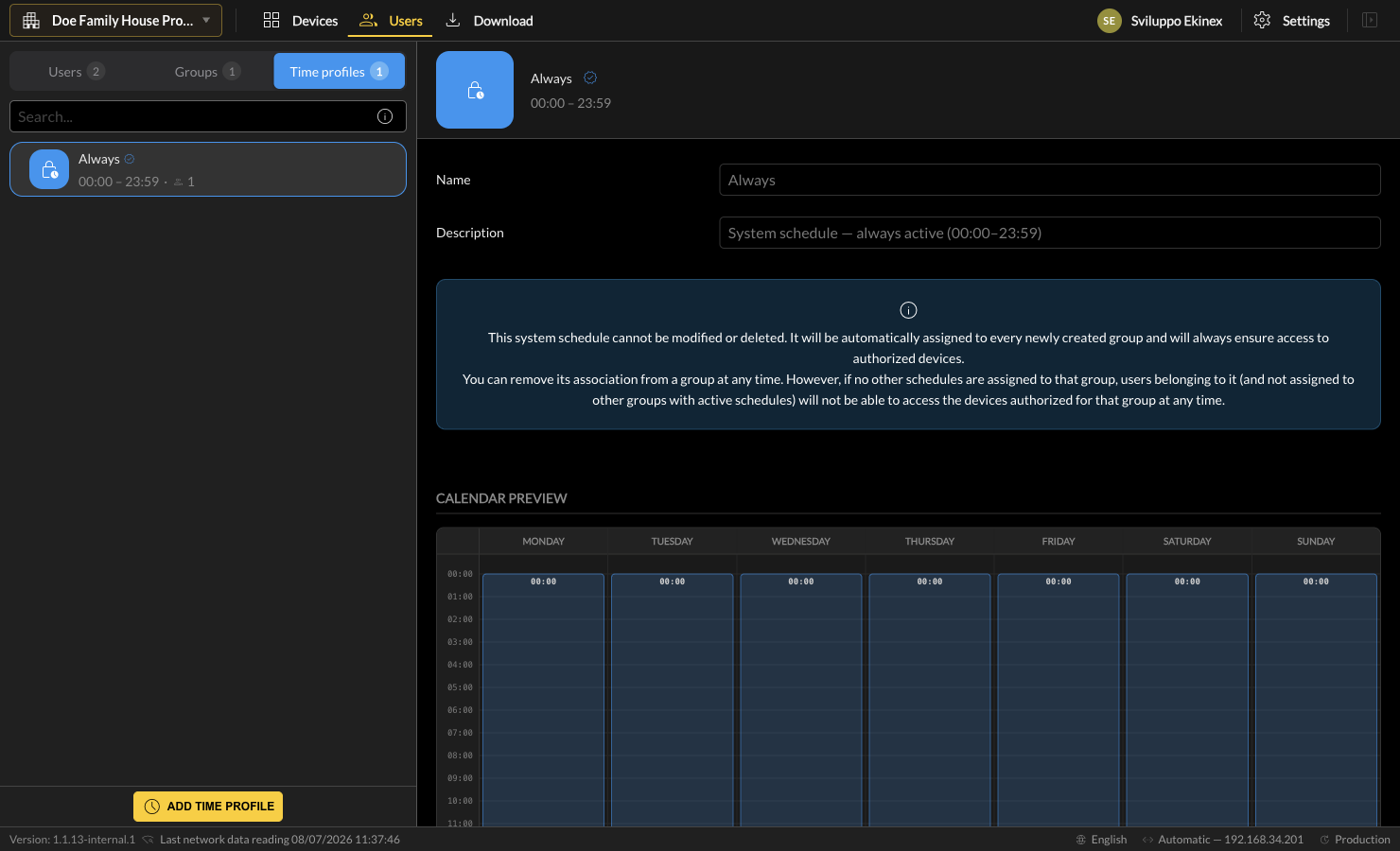
The Always system profile
Every project contains a built-in profile named Always (00:00–23:59, every day). It cannot be modified or deleted and is automatically assigned to every newly created group.
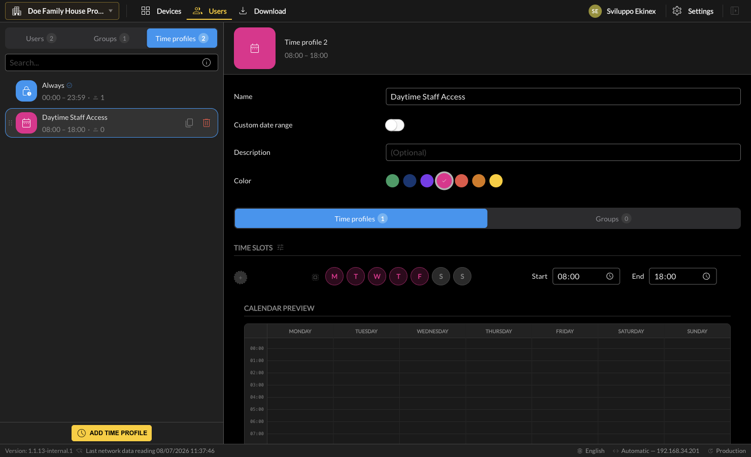
Creating a custom time profile
A custom profile is built from one or more time slots. For each slot you select the weekdays it applies to and its Start and End times. Enable Custom date range to further restrict the profile to a specific calendar period (for example a temporary guest access).

Restricting a profile to a calendar period (Custom date range)
By default a time profile repeats indefinitely, week after week. Enable the Custom date range toggle to make the profile valid only within a specific calendar period. Two date fields appear:
- From - the first date on which the profile is active.
- To - the last date on which the profile is active.
Outside this window the profile grants no access, regardless of its weekly time slots. This is the recommended way to model temporary access - for example a contractor or a holiday guest who should reach the devices only for a limited number of days.

Combining multiple time profiles (summation)
A group is not limited to a single schedule: it can be associated with several time profiles at the same time. When it is, the profiles are added together - the group's effective access window is the union of all its profiles. A moment grants access if it falls inside any of the associated profiles.
Add profiles to a group from the Time profiles tab of the group, using the Add time profile chip. The Calendar Preview immediately reflects the combined result.
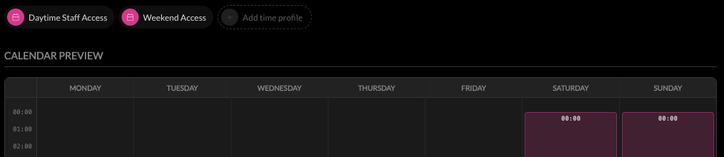
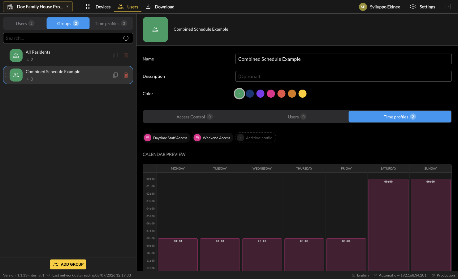
In the example below the group Combined Schedule Example is associated with two profiles:
- Daytime Staff Access - Monday to Friday, 08:00–18:00;
- Weekend Access - Saturday and Sunday, 00:00–23:59.
The calendar preview shows both contributions at once: the weekday daytime band and the full weekend columns.
Relationship combinations
The three subsections can be combined in several ways to model real access scenarios. The most common combinations are summarised below.
| Goal | Configuration |
|---|---|
| Permanent access for a household to a shared entrance | Group with the entrance device + the Always profile; add the household users as members. |
| Staff access on working hours only | Group with the relevant devices + a custom profile (e.g. Mon–Fri 08:00–18:00); add the staff users. |
| Temporary guest access | Custom profile with Custom date range limited to the stay; assign it to a dedicated group. |
| Different schedules on the same devices | Associate several time profiles with the same group, or create multiple groups over the same devices with different profiles. |
| A user with more than one access rule | Add the user to several groups; the effective access is the union of all groups (evaluated with each group's schedule). |
Project types: Apartments vs Villa / Building
The behaviour of the Users area differs depending on the project type chosen when the project was created. There are two families of behaviour.
Apartments-type projects
In an Apartments project the building is divided into residential units (apartments). Access management follows two rules:
- Apartment devices - implicit access. Each user must be assigned to an Apartment (User properties). The user then automatically inherits access to all devices located inside that apartment. No manual configuration is required, and this access is always granted.
- Public devices - explicit access. Access to public devices (common areas, entrances, condominium areas) is granted through the Groups subsection.
As a consequence, the Access Control tree of a group in an Apartments project lists only public devices. Apartment-internal devices are intentionally hidden, because they are handled automatically by the apartment assignment.

"For Building-type projects it is not possible to enable access to internal apartment devices. In this type of configuration, devices located within residential units are managed automatically: access permissions are assigned implicitly and are always granted to users associated with the respective apartment. Therefore, access groups may include only public devices, i.e. those located in common areas or outside apartments (for example entrances, shared spaces or condominium areas), while internal devices cannot be manually configured in access groups."
Villa and Building projects
In Villa and Building projects the apartment distinction does not exist. There is no implicit apartment inheritance and no public/internal separation: every device of the project - including devices nested under sub-nodes such as floors - can be selected in a group's Access Control tree. All access is therefore defined explicitly through groups.
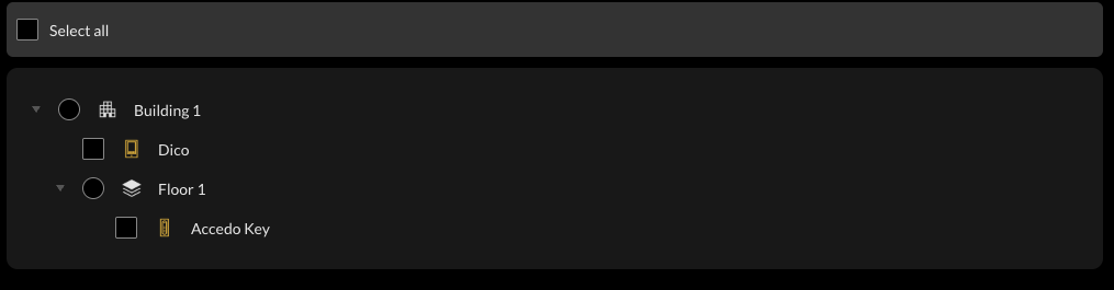
Side-by-side comparison
Apartments - public devices only
Villa / Building - all devices
| Apartments | Villa / Building | |
|---|---|---|
| User → Apartment | Required; grants implicit access to apartment devices | Not applicable |
| Groups → Access Control shows | Public devices only | All devices (incl. nested) |
| Internal / nested devices | Managed automatically (implicit) | Configured manually in groups |
Configuration case histories
This section applies everything described so far to two complete, real-world configurations - one for each project family. Each case history lists the device inventory, the step-by-step configuration recipe, and a summary of the resulting access.
Case 1 - Multi-apartment condominium
Device inventory
| Device | Type | Location | Access rule |
|---|---|---|---|
| Main Entrance | Dico | Public (building) | All residents, always |
| Pool | Dico | Public (building) | All residents, 08:00–22:00 |
| Accedo Key (Garden Unit) | Accedo Key | Inside Garden Unit | Implicit - Garden Unit residents |
| Accedo Key (Penthouse Unit) | Accedo Key | Inside Penthouse Unit | Implicit - Penthouse Unit residents |
Configuration recipe
- In Devices, add the two public door phones to the building and name them Main Entrance and Pool. Add one Accedo Key inside each apartment.
- Assign each user to its Apartment (User properties). This alone grants each resident implicit access to their own apartment's Accedo Key.
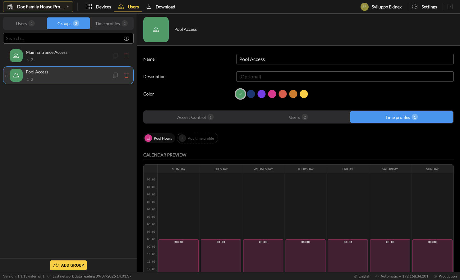
- In Time profiles, create Pool Hours - every day, 08:00–22:00.
- In Groups, create Main Entrance Access: authorise the Main Entrance device, keep the Always profile, and add all residents.
- Create Pool Access: authorise the Pool device, replace Always with Pool Hours, and add all residents.

Resulting access
Because both residents are members of both shared-device groups and assigned to their apartment, the Authorized devices tab of a resident summarises all three access sources at once.
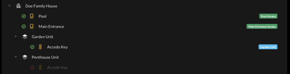
| User | Apartment | Groups | Reaches |
|---|---|---|---|
| Owner Garden Unit | Garden Unit | Main Entrance Access, Pool Access | Main Entrance (always), Pool (08–22), Garden Unit reader (implicit) |
| Owner Penthouse Unit | Penthouse Unit | Main Entrance Access, Pool Access | Main Entrance (always), Pool (08–22), Penthouse Unit reader (implicit) |
Case 2 - Independent house (Villa)
Device inventory
| Device | Type | Location | Access rule |
|---|---|---|---|
| Main Gate | Dico | Street gate | All family members, always |
| Main Entrance | Accedo Key | House door | All family members, always |
Configuration recipe
- In Devices, name the door phone Main Gate and the reader Main Entrance.
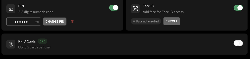
- In Users, create the four family members. For each, open the Credentials tab and enable both PIN (a unique code is generated automatically) and Face ID.
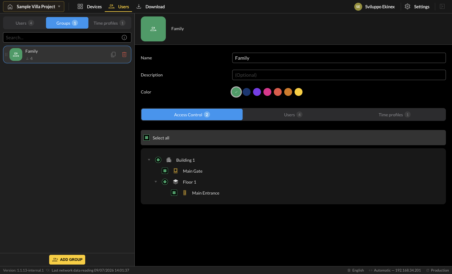
- In Groups, create a single Family group: authorise both devices, keep the Always profile, and add all four users. (In a Villa project every device - including the reader nested under the floor - is selectable.)
Resulting access

Download
Introduction
The configuration of the devices described in the previous chapters remains inside Ekinex Studio until a Download is performed into the actual devices. A project can be done entirely offline (dragging products from the Library instead of Discover) but, at some point, the actual devices must be associated with their MAC address and the configuration transferred to them.
Devices overview
Press the Download button in the top navigator to open the devices overview. In this version all the buildings of the project are shown together on the same screen; the previous Select building selector is no longer present. The devices are organised following the project tree, and each Building and Apartment group can be expanded or collapsed. A badge on each Building header reports how many of its devices still require a download.
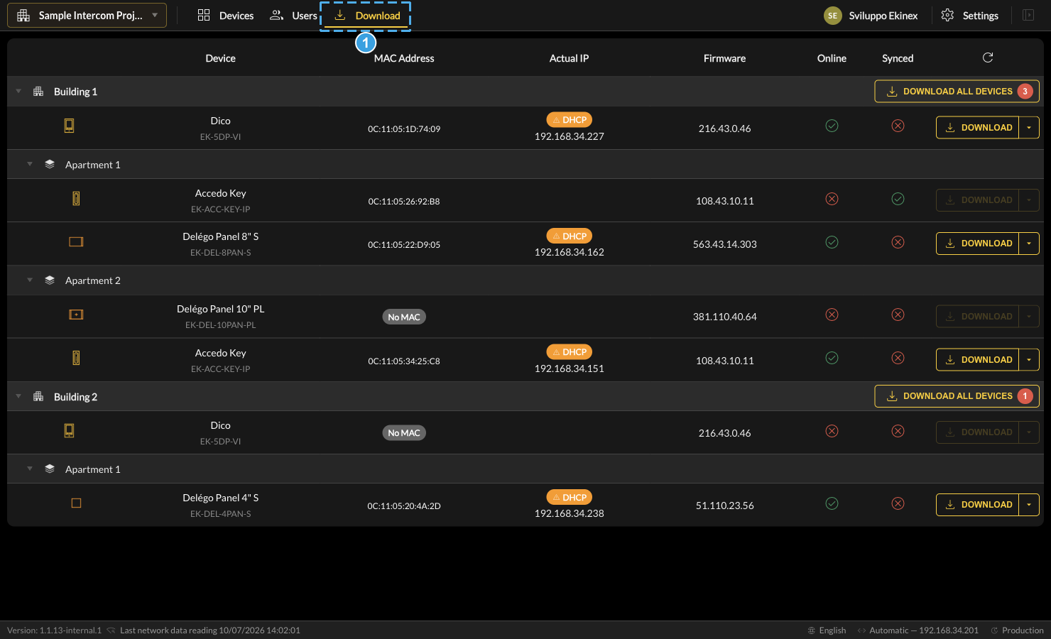
- Press Download in the top navigator to open the devices overview.
The device list contains:
| Device | Name of the device in the project and its product model. |
| MAC address | The unique MAC address of the device. |
| Network config | Network settings assigned to the device (Static IP or DHCP, IP address). May differ from the actual address, typically before downloading. |
| Actual IP | The actual network configuration detected on the device. |
| Firmware | The expected firmware version used for configuration. A different detected version is reported in red as a warning. |
| Online | Whether the device is detected on the network. |
| Synced | Whether the device is aligned with the project or needs a download. |
The last column indicates the device state and offers one of the following actions:
| Download | Transfers the configuration into the device (up to a minute; a progress bar indicates the advance). After a first full download, only effective changes are transferred. Button colour: yellow = changes to transfer, green = last download successful, red = error (details in the tooltip). |
| Update / Updating | A firmware update, or an alignment with the device's firmware version, is needed. Blue = update action available; gray = update already in progress (label becomes "Updating"). |
If the column is empty or a button is semi-transparent, the device cannot be reached at the moment. Example of multiple device states:
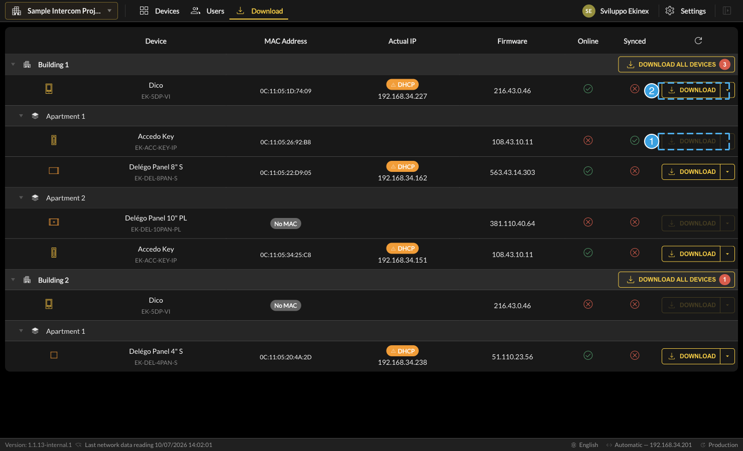
- A semi-transparent (grayed) Download button means the device cannot be reached at the moment, so the configuration cannot be written.
- A solid Download button means the device is reachable and ready to receive the configuration.
Cloud VPN
Introduction
Starting from version 1.1, it is possible to connect directly to the home network where DELÉGO SERVER is installed, from a PC / Mac, through a VPN connection based on the Ekinex cloud.
This connection is useful to remotely:
- Program KNX devices or do diagnostics with ETS PROFESSIONAL.
- Change the configuration of Ekinex connected devices (DICO intercom, Delego Panels etc.).
- Access any other network-based device, in the same way it would be possible being physically attached to the LAN.
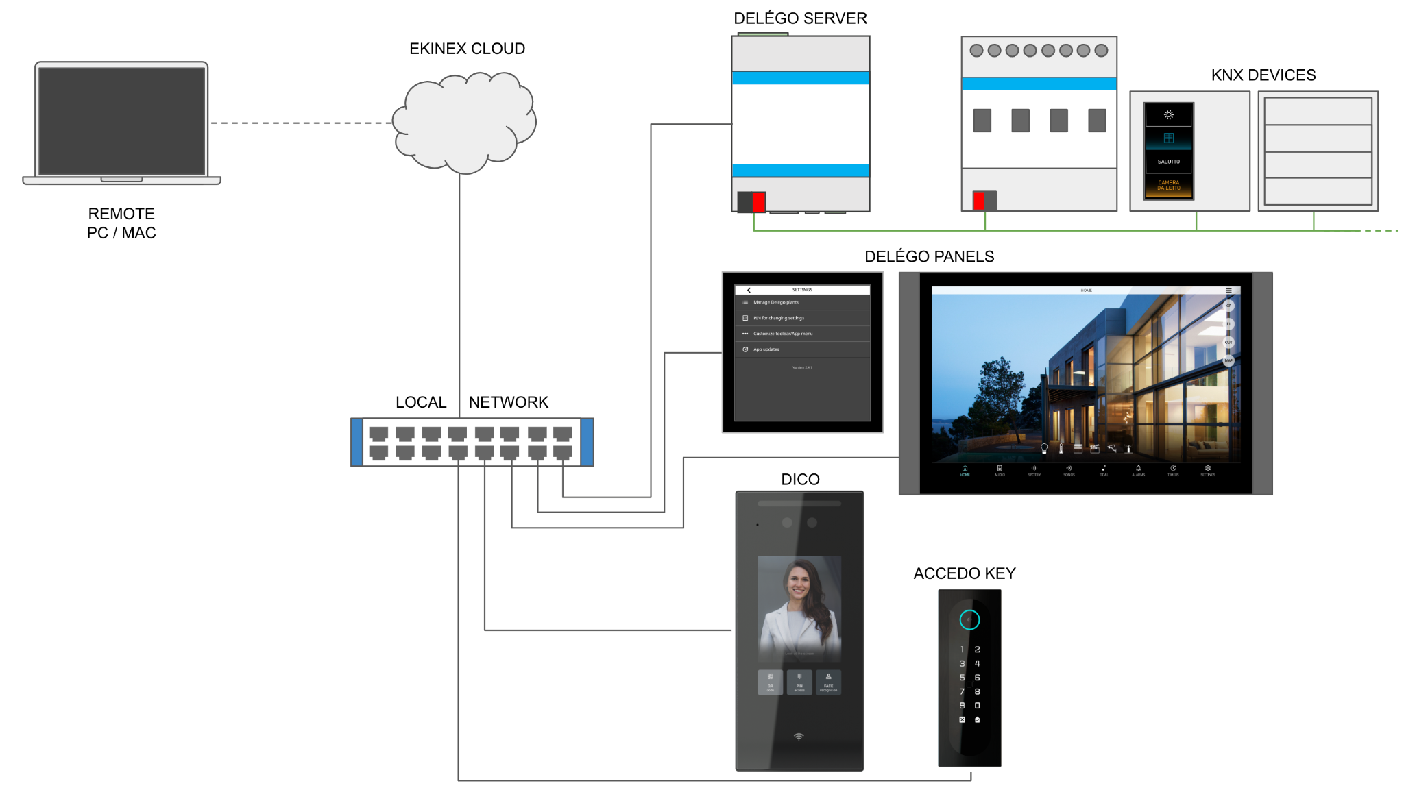
Each DELÉGO SERVER has its own dedicated VPN, isolated from the others, and uses the Wireguard tunnel technology, to ensure the maximum degree of robustness and security. No configuration is required on the internet router / firewall.
Cloud login
Before doing any configuration on the cloud VPN, at least one cloud account must be enabled and associated with DELÉGO SERVER.
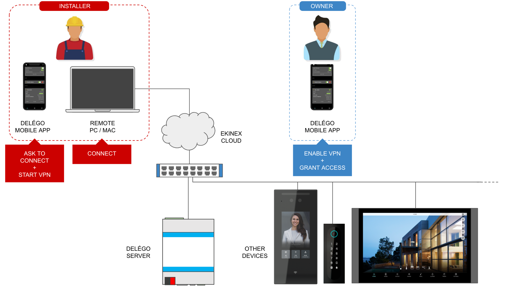
Being the cloud VPN a way to access the IP home network of the building, for security reasons, it is strongly recommended to differentiate the users by doing the following configuration:
- Create (at least) one DELÉGO SERVER user for the "property manager" of the building (e.g. the home holder) and bind it as OWNER to his / her cloud account.
- Dedicate a different DELÉGO SERVER user to the installer / system integrator, binding it as INSTALLER to the corresponding cloud account
In this way:
- The owner can (with the Délego mobile app)
- enable or disable the VPN at any moment.
- grant the access for the installer(s).
- The installer can (with the Délego mobile app)
- ask to connect (if the VPN is disabled, or the account is not granted).
- start and stop the VPN.
- (with the PC / Mac)
- connect to the home network.
Service activation
In the administration area, after having done a cloud login with a valid Ekinex cloud account, select the following item in the tree menu
SETUP > EKINEX CLOUD > CLOUD SERVICES
and identify the VPN service, like in the following screenshot:

Press the ACTIVATE button and wait until the list reloads, and the service becomes active.
VPN creation
Once the VPN service has been activated, enter the section
SETUP > EKINEX CLOUD > VPN
and enter a name, to be associated with the VPN. This name will be reported in email and push messages, therefore it is suggested to give a name reminding the building / installation.
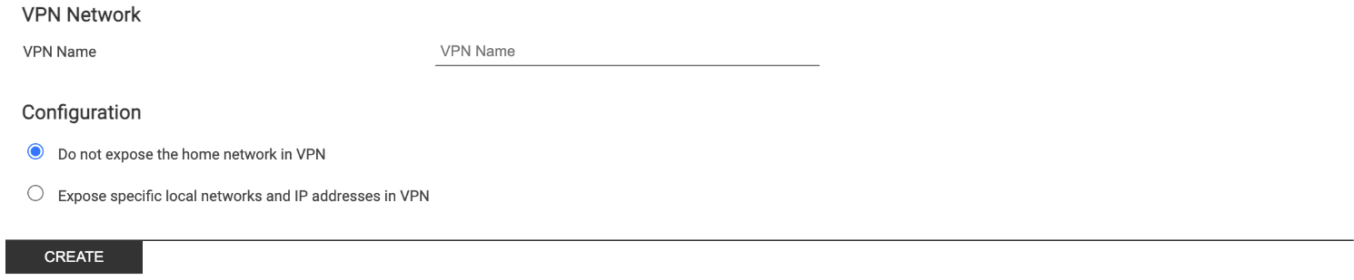
By default, for security reasons, DELÉGO SERVER does not allow access to any other device in the home network (LAN) except itself.
It is possible to optionally expose one or more devices, or network subnets, by entering the following information:
- To expose a single IP address, enter it in the text fields, and press ADD.
- To expose a subnet, enter only the first parts of the address, by leaving empty the last part(s). In this case, all the IP devices matching the entered numbers, will be reachable remotely
| DELEGO SETTING | CIDR NOTATION | REACHABLE IP ADDRESS(ES) |
|---|---|---|
| 192.168.1.1 | 192.168.1.1/32 | 192.168.1.1 |
| 192.168.1.XXX | 192.168.1.0/24 | 192.168.1.1 192.168.1.2 [...] 192.168.1.254 |
| 192.168.XXX.XXX | 192.168.0.0/16 | 192.168.1.1 192.168.1.2 [...] 192.168.1.254 192.168.2.1 [...] 192.168.254.254 |
Press the CREATE button and wait until the VPN information will appear in the page.
Otherwise, DELÉGO SERVER will be only reachable with its VPN address, as shown below.
Deselect the corresponding flag and press the UPDATE button to make it disabled by default; the owner(s) will enable it with the Délego mobile app, as described below.
Connections
In order to connect to the VPN, installers must own one or more CONNECTION(s) for each PC / Mac they will use to remotely access the home network.
Press the ADD button and enter the following information:
- A label that identifies the PC / Mac used for the connection.
- The cloud account associated with the connection.
- The enable (grant) status of the connection.
- Create a new local user in DELÉGO SERVER in the USERS AND PERMISSIONS section
- Enter with these credentials and login with the desired cloud account in the SERVICES > CLOUD > PRODUCT REGISTRATION
- Bind the cloud account as OWNER or INSTALLER by pressing the corresponding button (once the cloud login has been done)
Once pressed the SAVE button, two buttons will be enabled:
- The DOWNLOAD button is used to download the configuration file, necessary to set up the VPN connection on the PC/Mac of the installer that needs to connect to DELÉGO SERVER.
- The QR CODE button is used to download the QR code that can be used on a VPN tool to set up automatically the VPN connection to DELÉGO SERVER.
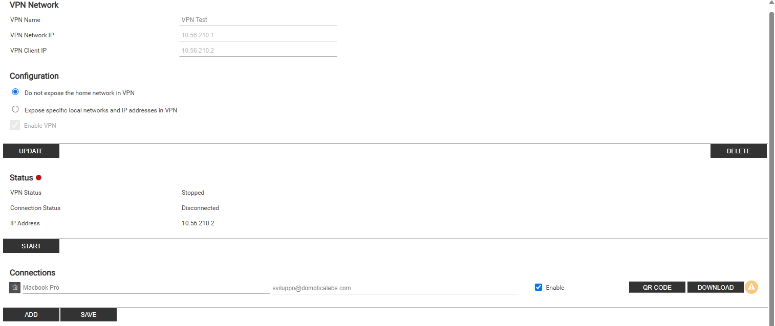
In that situation, a yellow warning indicator blinks close to the connections to be downloaded again.
Starting and stopping the VPN
The default state of a VPN is stopped and must be manually started when there is the need to remotely connect to the home network. This can be done by pressing the START button in the VPN configuration page in DELÉGO SERVER, or with the mobile app (as described in the dedicated section later). A VPN connection will stay active for 2 hours; after 2 hours it will stop. To stop it manually, press the STOP button, when it is no longer needed.
The STATUS section contains also the IP address of DELÉGO SERVER in the VPN:
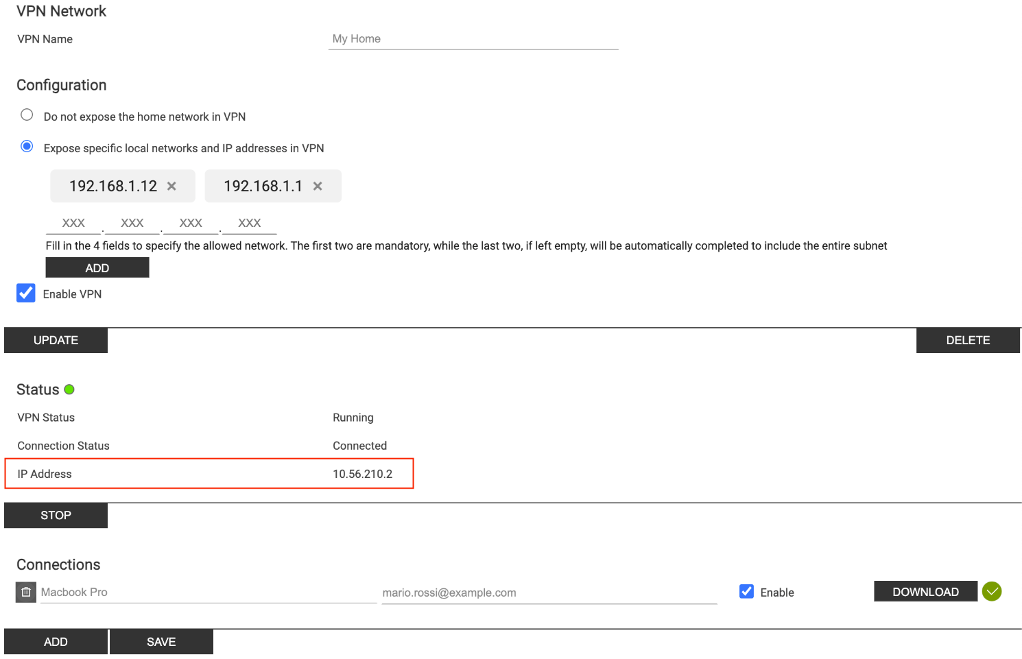
Use this IP address to "point" to the webserver, in order to:
- Access its web pages .
- Use it as an IP interface for ETS PROFESSIONAL.
Control with the mobile app
Requirements
The Délego mobile app can be used to control the VPN associated with a DELÉGO SERVER. In order to do so, the following requirements must be met:
- An Ekinex cloud account must be entered in the settings area of the app
- At least one DELÉGO SERVER must be configured with a valid cloud remote address
- The DELÉGO SERVER(s) must be associated with the entered cloud account, with OWNER or INSTALLER rights
The VPN enabled projects show a "lock" symbol on the right in the title:
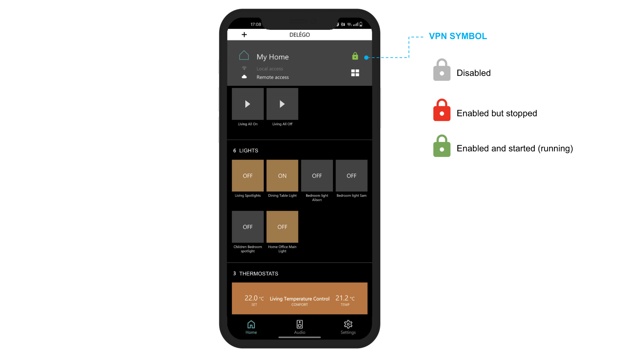
When pressed, this symbol opens the VPN control screen, as better illustrated in the following paragraphs.
Owner view
The following picture shows the typical VPN section content for an owner account:
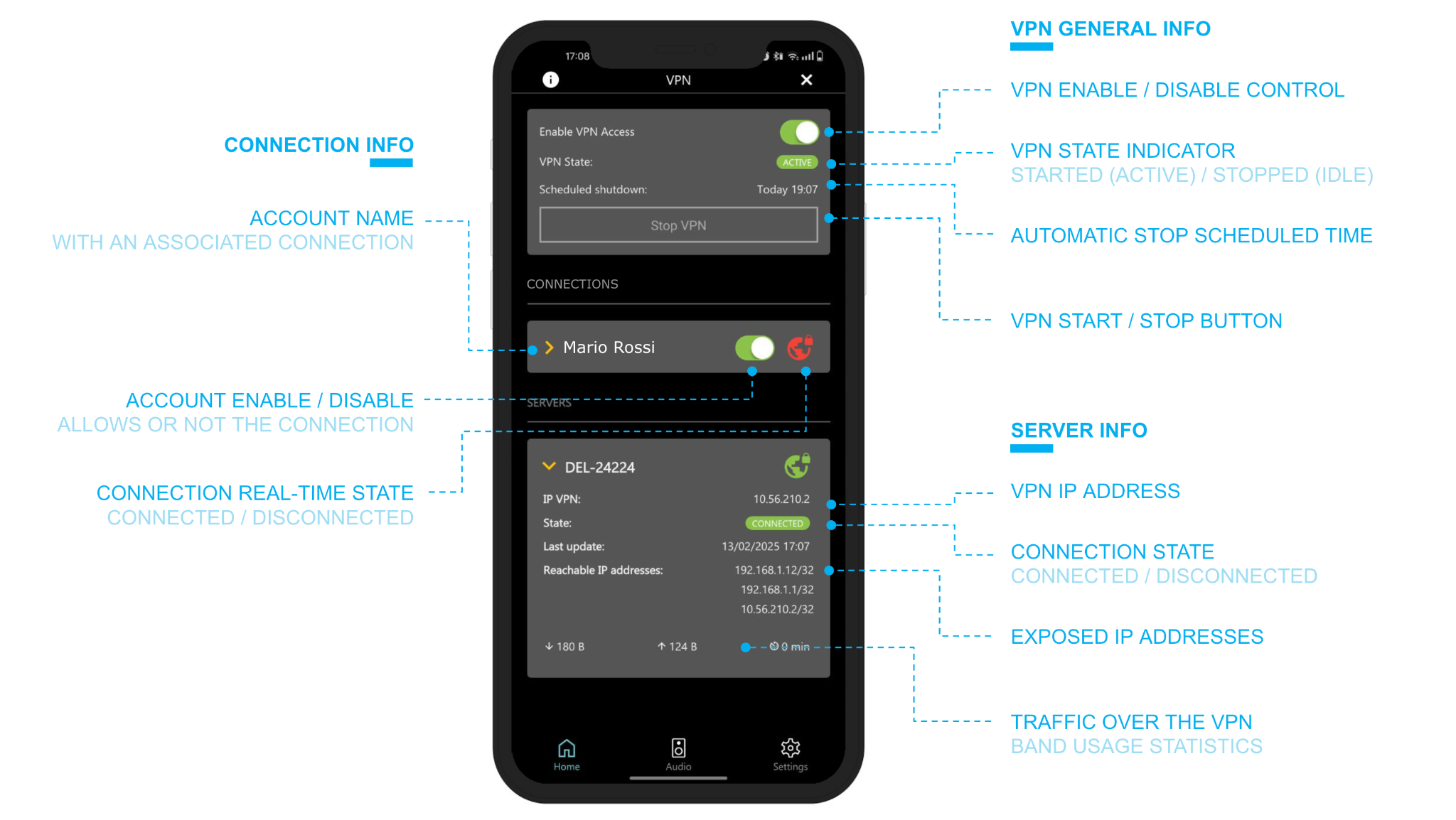
Each account with an associated connection, can be enabled or not, by acting on the corresponding control: in general, a VPN can be enabled (green indicator in the initial part of the screen) but the single users can be disabled. In this case, they cannot connect. When a user connects through one of these connections, the state goes to green.
The server info section contains details about the connection of the webserver to the VPN, its IP address, and all the other reachable IP addresses.
If the VPN is not enabled, all the contents are hidden, and the only possible action is to enable it:
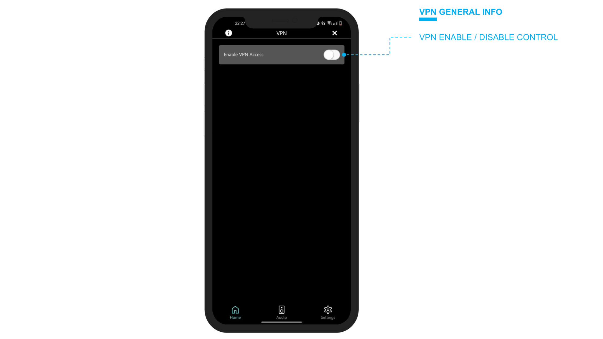
Each account with an associated connection, can be enabled or not, by acting on the corresponding control: in general, a VPN can be enabled (green indicator in the initial part of the screen) but the single users can be disabled. In this case, they cannot connect. When a user connects through one of these connections, the state goes to green.
Installer view
The VPN section view for an installer, contains fewer information, like in the following example:
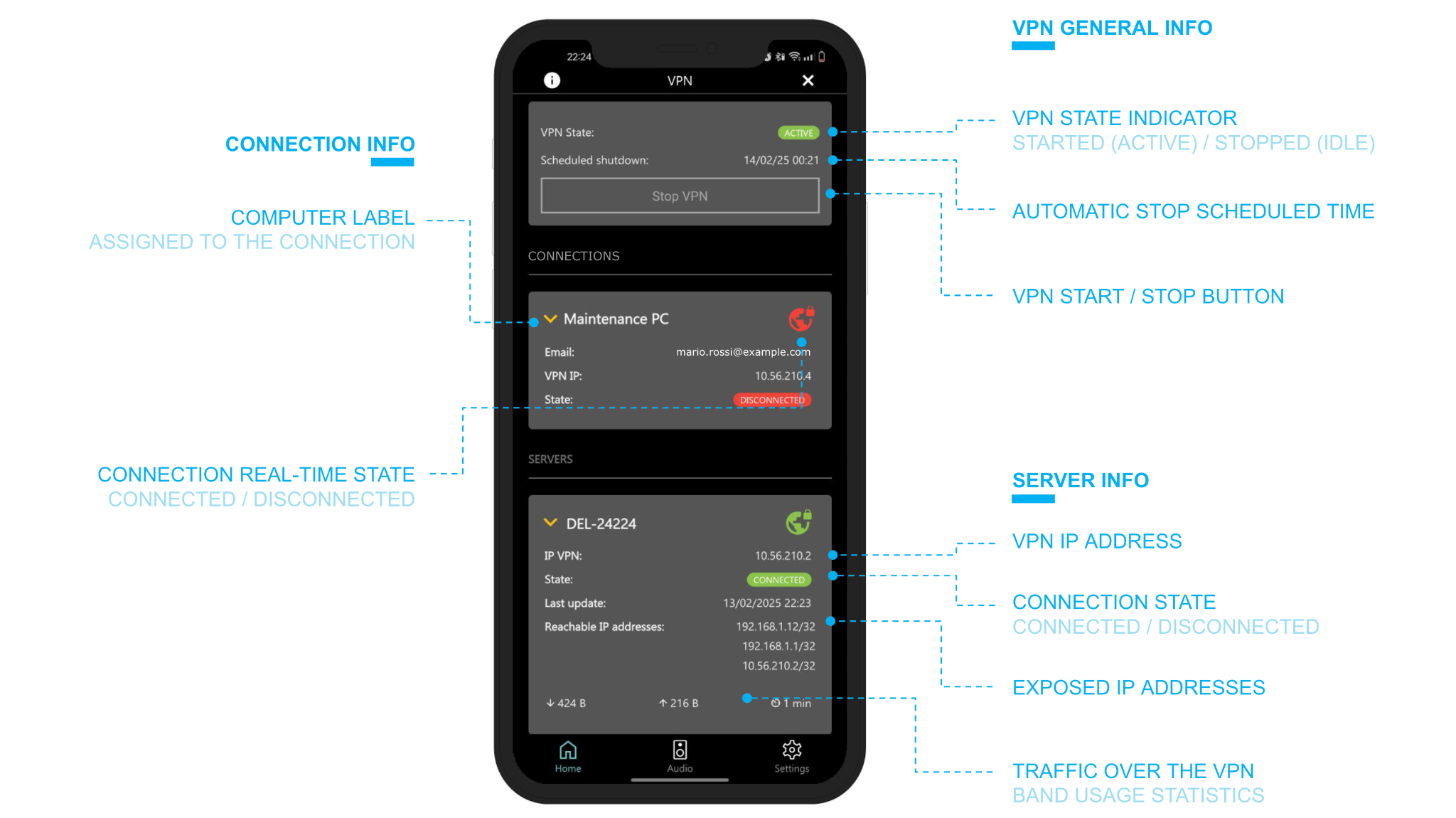
If the VPN is disabled, or the installer is not granted to connect, the only allowed action is to send a request to connect:
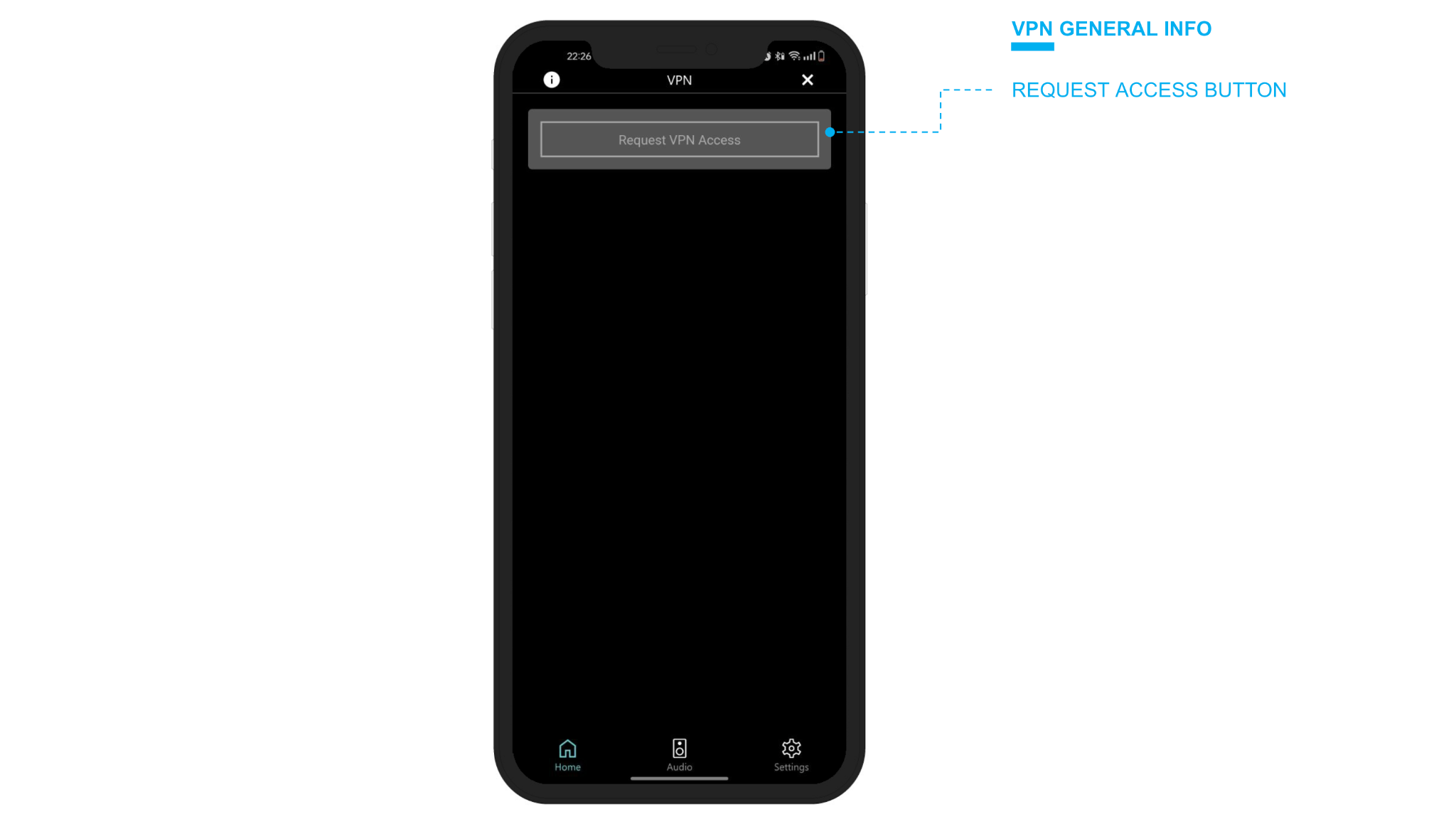
Notifications
When an installer asks to connect, a push notification and an email message are immediately sent to all the owners of the webserver. By pressing on the notification, the DÉLEGO mobile app is opened directly in the section of the interested VPN: it is just needed to act on the ENABLE controller.
Push notifications and email messages are also sent when:
- A VPN is enabled or disabled.
- A VPN is started or stopped.
- A connection (user) is granted or not.
Remote VPN Connection
Cloud login
Connecting to your systems via VPN requires authentication with your EKINEX cloud account, the same one used to authenticate on Ekinex Studio, as illustrated in Ekinex cloud account.
Accessing the VPNs
If the connection to the cloud is successful, a menu appears in the system bar containing the list of CLOUD VPNs to which your account has access.
If one or more web servers have also been configured as systems (see next point) they appear at the beginning of the list, vice versa they are listed in the "OTHER VPNs" section, as in the following example (which shows the MAC version):
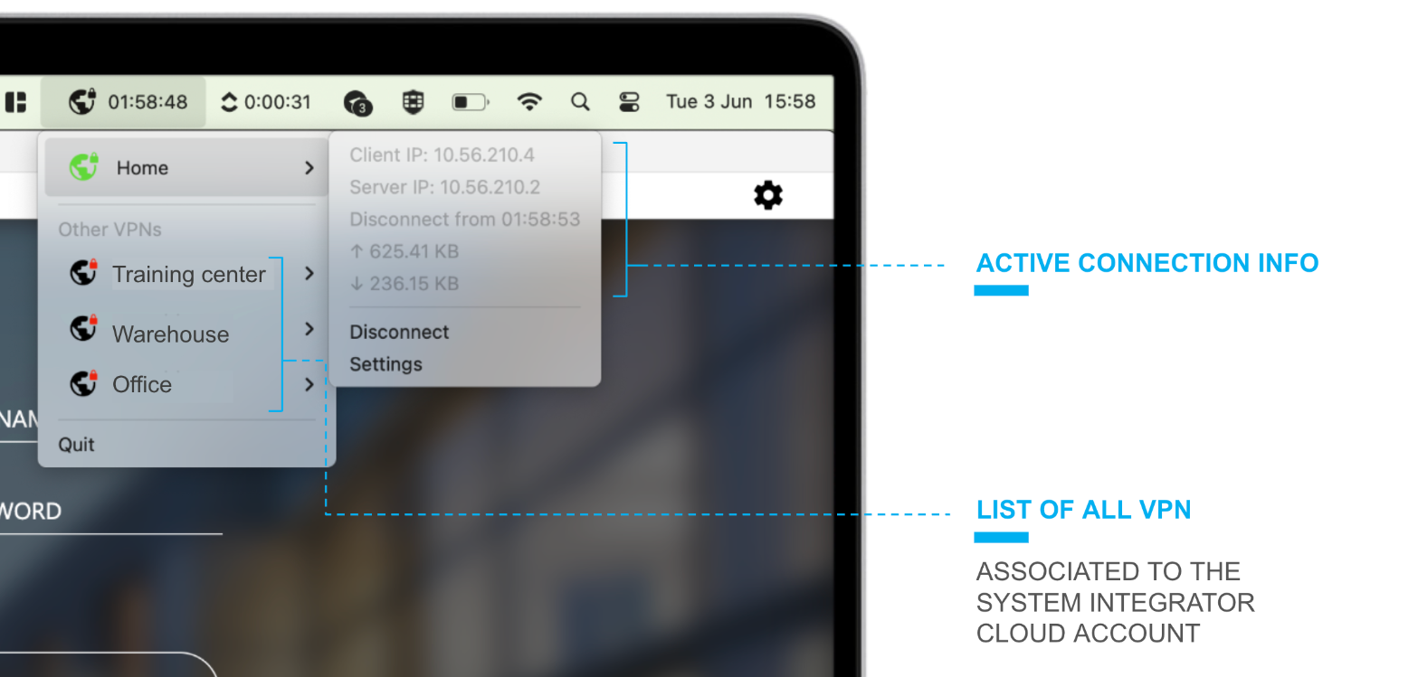
The first time you connect to a VPN, you need to press the SETTINGS item; a screen similar to the following is displayed:
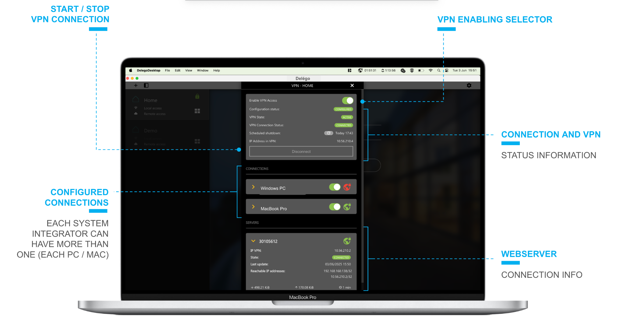
In the CONNECTIONS section, a new connection is automatically created for your PC / MAC, associated with your cloud account. This connection is initially disabled; if you have an installer profile, you must request access via the appropriate button at the top of the popup, and wait for the building owner to authorize your user to connect.
If, on the other hand, you are the owner, you can enable the connection, with the appropriate selector.
By pressing the CONNECT button, you can establish a connection to the building's local network through the CLOUD VPN; after a few seconds, the status indicators turn green, and the statistics on connection time and exchanged data traffic begin to update.
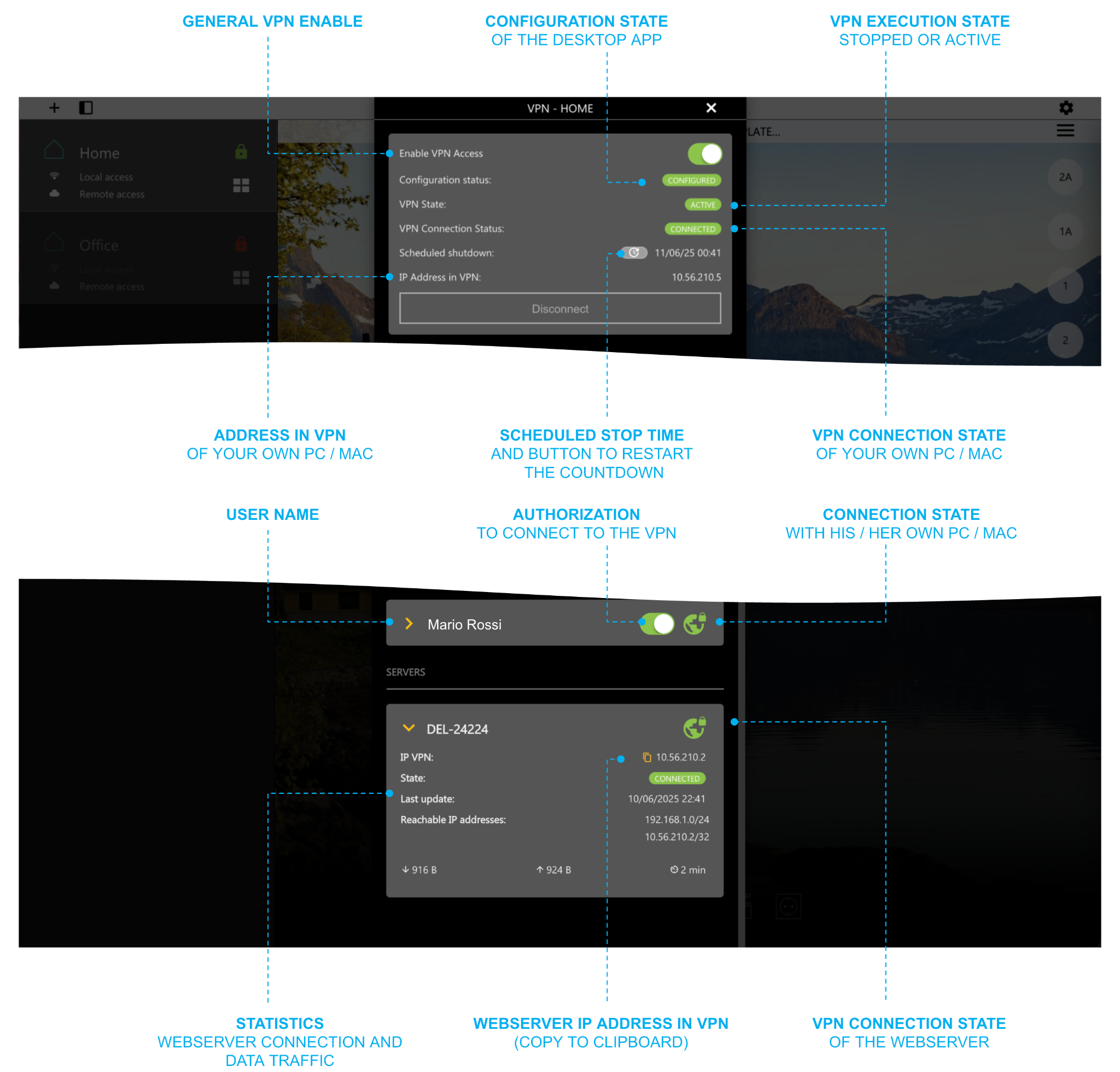
The IP address of the web server in the VPN is shown in the section below, containing the server data; you can copy it to the clipboard with the appropriate button, to be able to easily insert it into other applications (e.g.: ETS professional).
After the first connection, you can monitor connection statistics, start or stop the connection, directly from the system tray. It also displays'also the time remaining before the connection automatically stops, and it is possible (via the dedicated button, by opening the settings) to reset the countdown, if the maintenance intervention requires more than 2 hours.